Computer Architecture
Hardware
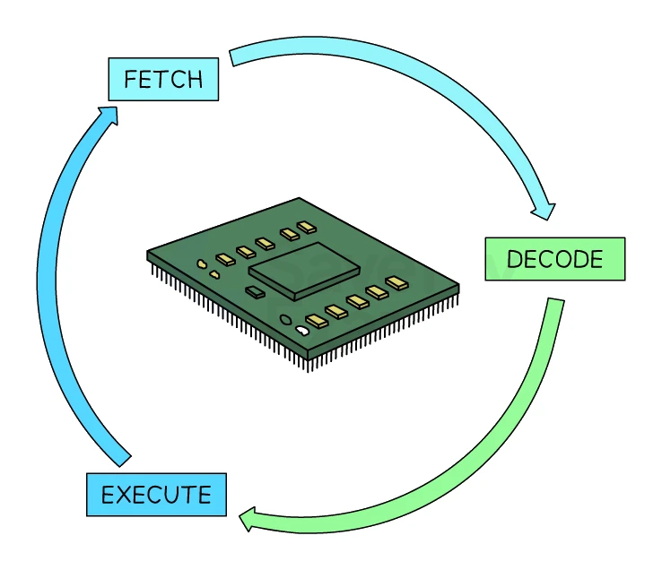
The CPU runs the same three-step cycle, over and over, billions of times per second.
Stage 1: Fetch
The CPU pulls the next instruction from memory.
- The PC holds the address of the next instruction.
- The address in the PC is copied into the .
- The address is placed on the and sent to memory.
- The sends a "memory read" signal along the control bus.
- Main memory responds by placing the instruction at that address onto the .
- The instruction travels along the data bus into the .
- A copy of the instruction is transferred from the MDR into the .
- The PC is incremented by 1 so it now points to the next instruction in sequence.
Stage 2: Decode
The CPU works out what the instruction means.
- The Control Unit takes the instruction from the CIR.
- The instruction is split into two parts:
- Opcode: which operation to perform (e.g. ADD, SUB, LOAD, STORE)
- Operand: what value or address to operate on
- The CU works out what control signals will be needed for the execute stage.
Stage 3: Execute
The CPU carries out the instruction.
Depending on the opcode, this might involve:
- The ALU performing an arithmetic or logical operation (the result goes into the ACC).
- Reading data from memory (using the MAR, MDR and the buses again).
- Writing data to memory.
- Jumping the PC to a different memory address (changing the order of execution, e.g. for an
IFstatement or a loop).
After the execute stage, the cycle starts again with the fetch stage, using the new value of the PC.
The cycle in one line
Fetch (PC → MAR → address bus → memory → data bus → MDR → CIR; PC++)
Decode (CIR → CU splits into opcode + operand)
Execute (, memory, or PC jump; results often in ACC)
Common exam question
Describing the decode stage
Question: Describe what happens at the decode stage of the cycle, or complete and annotate a diagram to show how an instruction is decoded once it has reached the MDR (3–4 marks).
Asked in 2 of the 17 papers, one mark per point, so give three or four ideas: the instruction is sent from the MDR to the CIR, which is built into the control unit; it travels along the data bus; it is split into an opcode and an operand; the control unit decodes it; and it does so using the instruction set. In the diagram version only the MDR is printed: add the CIR, an arrow from MDR to CIR labelled with the data bus, and labels saying the control unit decodes the instruction using the instruction set; each correct labelled part is a mark. The full list of machine-code commands a CPU can process is its instruction set, itself a one-mark naming question.