Current, Potential Difference & Resistance
Electricity
What resistance is
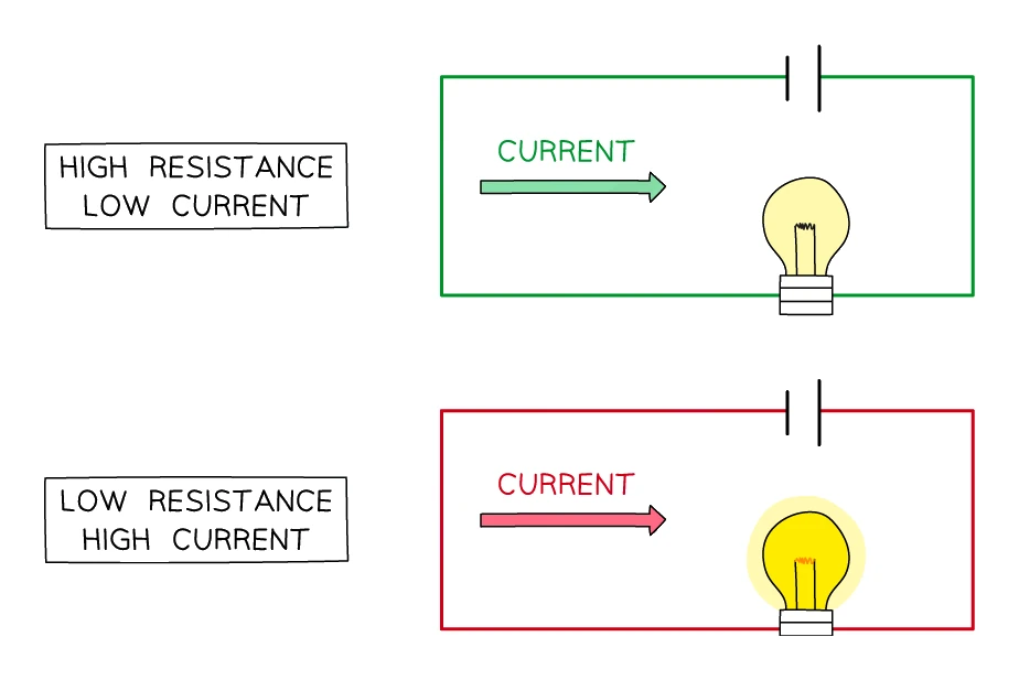
- Resistance is the opposition a component offers to the flow of electric current through it
- The greater the resistance, the harder it is for charge to flow, and so the smaller the current for a given voltage
- Resistance is measured in ohms, symbol Ω (the Greek capital omega)
- A component has a resistance of 1 Ω when a voltage of 1 V across it drives a current of exactly 1 A through it (so 1 Ω = 1 V/A)
What sets the resistance of a component
- Material: good conductors like copper and silver have very low resistance; insulators like rubber and dry wood have enormous resistance
- Length: a long wire has more resistance than a short one of the same material and thickness, because every extra metre adds to the obstruction
- Cross-sectional area: a thick wire has less resistance than a thin one, because there is more room for charge to flow
- Temperature: in most metals, resistance rises as temperature rises; the metal ions vibrate harder and collide with the drifting electrons more often
- Even the connecting wires themselves have a small resistance, but in exam circuits they are taken to be zero unless the question states otherwise
Ohm's law: V = I × R
- The defining equation linking voltage, current and resistance is:
V = I × R
- where:
- V = voltage across the component (V)
- I = current through the component (A)
- R = resistance of the component (Ω)
- Rearrangements:
- I = V / R (current is voltage divided by resistance)
- R = V / I (resistance is voltage divided by current, which is the experimental way to measure R)
- A component is said to be ohmic if its resistance is constant across the working range (V is then directly proportional to I). Many resistors and lengths of metal wire at a steady temperature behave this way; filament lamps and diodes do not, and so are non-ohmic (covered fully in topic 06)
Common exam question
Stating the formula linking three quantities
Question: State the formula that links voltage, current and resistance, or charge, current and time, or energy transferred, charge and voltage (1 mark).
Asked in 12 of the 24 papers, most often for voltage = current × resistance. Words or standard symbols both score, in any rearrangement: V = I × R, Q = I × t or E = Q × V, or I = V/R and the like. Two habits can lose the mark. A formula written in units, such as V = A × Ω, is not a formula and is ignored. And C is the symbol for coulombs, not for current: schemes at best ignore a "C" written for current or charge and at worst reject it, so use I for current and Q for charge.
Common exam question
Calculating current, voltage or resistance with V = IR
Question: Calculate the current in a component, the voltage across it or its resistance, sometimes from a current read off a graph or with the unit to give (2–5 marks).
Set in 9 of the 24 papers. For the current or the resistance, the three-mark version gives one mark each for substitution, rearrangement and evaluation; R = V/I written anywhere in the working earns the rearrangement mark, and a power-of-ten slip costs one mark, so an answer out by a factor of a thousand still scores two. Convert mA to A and kΩ to Ω before substituting; one scheme makes that conversion its own mark.
When the current must be read from a graph at the stated voltage, the reading has a small tolerance and, in the five-mark version, a mark of its own. When the component shares the supply with another, use the voltage across the component itself: the supply voltage minus the voltage across the other component.
Worked example
Finding resistance from voltage and current
A resistor has a voltage of 9.0 V across it and a current of 0.30 A through it. Calculate its resistance.
Solution:
- Write the equation: V = I × R, so R = V / I
- Substitute: R = 9.0 / 0.30
- R = 30 Ω
Idealisations on circuit diagrams
- In exam questions, unless stated otherwise:
- the wires have zero resistance
- the internal of the cell or battery is zero
- an has zero resistance and so does not alter the current it is reading
- a has infinite resistance and so draws no current away from the component it is reading
- These idealisations make the algebra clean; in real life, every one of them is a small approximation rather than an exact truth