Exam Frequency Analysis
Past paper frequency (2018 to 2024)
This topic accounts for approximately 9% of your exam marks.
stable
Medium
Stable9%
Truth tables and Boolean expressions from circuit diagrams appear in every paper. 4 to 6 marks.
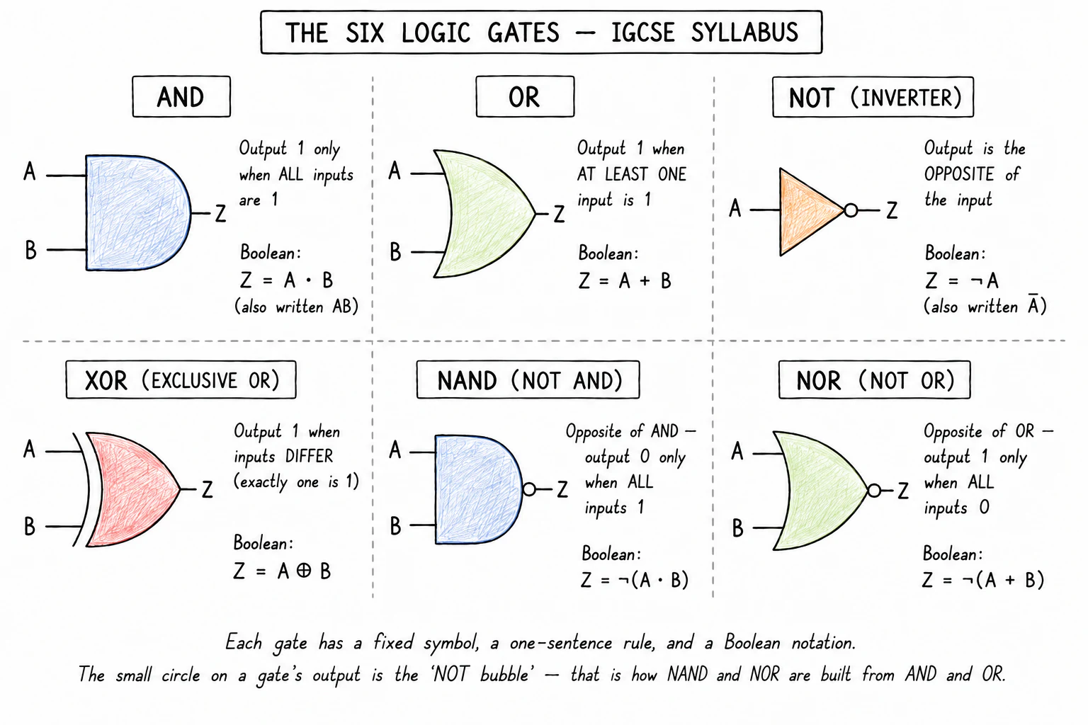
For each gate the format is the same: the rule in plain English, the Boolean notation accepted by examiners, and the truth table.
AND
Rule: the output is 1 only when every input is 1. If any input is 0, the output is 0.
| Boolean notation | Read aloud |
|---|---|
A · B, AB, A ∧ B | "A AND B" |
| A | B | A AND B |
|---|---|---|
| 0 | 0 | 0 |
| 0 | 1 | 0 |
| 1 | 0 | 0 |
| 1 | 1 | 1 |
A quick way to remember the rule: an AND gate is like two switches in series; current only flows through if both are closed.
OR
Rule: the output is 1 when at least one input is 1. The output is 0 only when every input is 0.
| Boolean notation | Read aloud |
|---|---|
A + B, A ∨ B | "A OR B" |
| A | B | A OR B |
|---|---|---|
| 0 | 0 | 0 |
| 0 | 1 | 1 |
| 1 | 0 | 1 |
| 1 | 1 | 1 |
Think of an OR gate as two switches in parallel: closing either one (or both) lets current flow.
NOT
Rule: the output is the inverse of the input. A 1 becomes a 0; a 0 becomes a 1. NOT has exactly one input.
| Boolean notation | Read aloud |
|---|---|
¬A, A̅, NOT A | "NOT A" |
| A | NOT A |
|---|---|
| 0 | 1 |
| 1 | 0 |
A NOT gate is also called an because it flips its input.
XOR (exclusive OR)
Rule: the output is 1 when exactly one input is 1. If both inputs are the same (both 0 or both 1), the output is 0.
| Boolean notation | Read aloud |
|---|---|
A ⊕ B, A XOR B | "A XOR B" |
| A | B | A XOR B |
|---|---|---|
| 0 | 0 | 0 |
| 0 | 1 | 1 |
| 1 | 0 | 1 |
| 1 | 1 | 0 |
The easiest way to keep XOR straight: the output is 1 when the inputs differ, and 0 when they match.
NAND (NOT AND)
Rule: the output is the opposite of AND. NAND outputs 0 only when every input is 1; in every other case the output is 1.
| Boolean notation | Read aloud |
|---|---|
¬(A · B), A NAND B | "A NAND B" |
| A | B | A NAND B |
|---|---|---|
| 0 | 0 | 1 |
| 0 | 1 | 1 |
| 1 | 0 | 1 |
| 1 | 1 | 0 |
NAND is drawn as an AND gate with a small circle on the output. The circle is the "NOT bubble" and it flips the result.
NOR (NOT OR)
Rule: the output is the opposite of OR. NOR outputs 1 only when every input is 0; in every other case the output is 0.
| Boolean notation | Read aloud |
|---|---|
¬(A + B), A NOR B | "A NOR B" |
| A | B | A NOR B |
|---|---|---|
| 0 | 0 | 1 |
| 0 | 1 | 0 |
| 1 | 0 | 0 |
| 1 | 1 | 0 |
NOR is drawn as an OR gate with the same NOT bubble on the output.
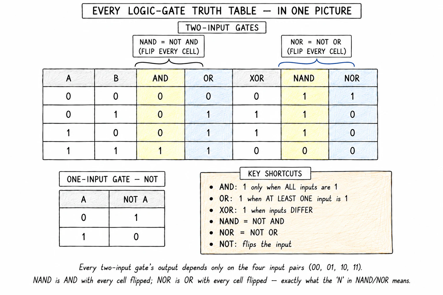
Side-by-side comparison
It is worth memorising this single table; almost every logic-gates question depends on it.
| A | B | AND | OR | XOR | NAND | NOR |
|---|---|---|---|---|---|---|
| 0 | 0 | 0 | 0 | 0 | 1 | 1 |
| 0 | 1 |
Two patterns are worth noticing:
- The NAND column is the AND column with every value flipped.
- The NOR column is the OR column with every value flipped.
That is exactly what the "N" in NAND and NOR means.