0984
Boolean Logic and Expressions
Boolean Logic · 5 question types
The three representations of a Boolean function can be converted in any direction. Each conversion has been covered above, but it helps to see them together.
| From → to | Method (covered in) |
|---|---|
| Circuit → expression | Label each gate's output with its sub-expression, working left to right (section 3). |
| Truth table → expression | One AND term per Q = 1 row, OR them together (section 4). |
| Expression → truth table | Evaluate the expression for every possible combination of inputs (section 5, repeated for each row). |
| Expression → circuit | One gate per operator; bracket innermost first; NOT gates before the negated signal feeds its next gate (covered in topic 26). |
| Circuit → truth table | Trace signals through each gate for every input row, adding intermediate columns (covered in topic 26). |
| Truth table → circuit | Derive the expression from the truth table, then draw the circuit for that expression. |
The circuit below can be taken either way: label each gate's output to build the Boolean expression for X, or trace every input combination through the gates to fill in its truth table.
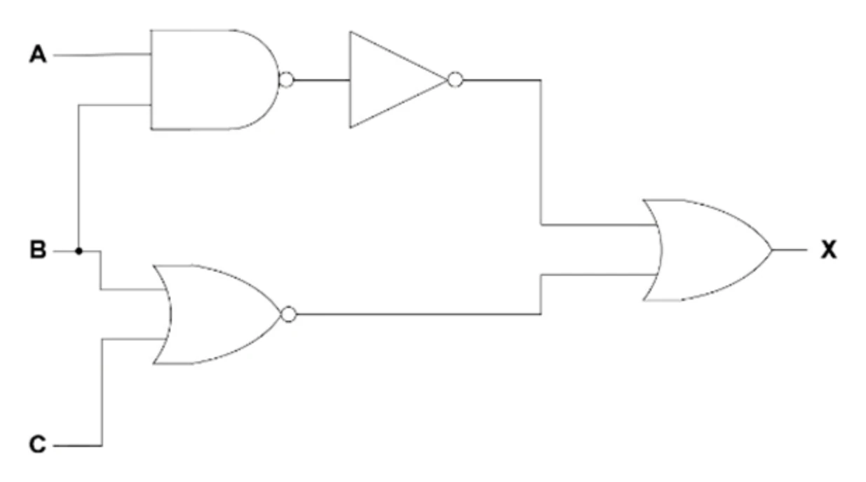
Whatever route the exam asks for, the key check is the same: at the end, the truth table of the new representation must agree with the truth table of the original, row for row.