1. Magnetism
Poles and the law of magnetism
- Every magnet has two poles: a north pole and a south pole
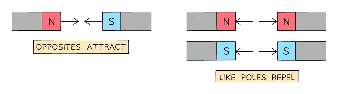
- Bringing two magnets close together produces a force between them. The direction of the force follows the law of magnetism:
- Like poles repel: N–N pushes apart; S–S pushes apart
- Opposite poles attract: N–S pulls together
- The force between two magnets is a non-contact force, so the magnets feel each other across an air gap without any physical link
Magnetic and non-magnetic materials
- A magnetic material is one that is attracted to a magnet (whether or not it is itself a magnet). The standard list is:
- iron
- cobalt
- nickel
- steel (an alloy of iron, so it counts)
- Almost every other metal is non-magnetic: copper, aluminium, gold, silver, lead, brass
- Non-metallic materials (plastic, wood, glass, rubber) are non-magnetic
- A magnetic material is attracted to either pole of a permanent magnet; only a magnet itself can be repelled by another magnet. So a quick test for whether an unknown bar of iron-coloured metal is a magnet or just a magnetic material: bring a known magnet near both ends in turn. If one end repels, you've found a magnet; if both ends only attract, it is a magnetic material
Hard and soft magnetic materials
- materials (e.g. steel) are difficult to magnetise, but once magnetised they hold their magnetism for a long time. They are used for
- materials (e.g. pure iron) are easy to magnetise, but lose their magnetism almost immediately when the magnetising field is removed. They are used for the cores of because you want the magnetism to switch off when the current does
Common exam question
Why steel makes a permanent magnet and iron does not
Question: Explain why steel suits a bar magnet, describe what magnetically hard means, name a permanent-magnet material, or explain why iron magnetised in a field is not a permanent magnet (1–2 marks).
Asked in 5 of the 24 papers. For steel the two marks are that it is magnetic and that it therefore stays magnetised for a long time; one scheme gives both marks for "steel is a hard magnetic material" on its own, so call it magnetically hard, and any mention of charge is rejected. Defining magnetically hard needs two of: difficult to magnetise, difficult to demagnetise, retains its magnetism. For a named material give steel, nickel, cobalt or neodymium; iron is only condoned.
For iron the pair is reversed: it is magnetically soft, so it loses its magnetism as soon as it leaves the field. Calling it "a soft magnet" or "a temporary magnet" earns nothing.
2. Magnetic fields
What a magnetic field is
- A magnetic field is the region around a magnet in which a force would act on another magnet, or on a piece of magnetic material placed within it
- Magnetic fields are visualised using magnetic field lines:
- The direction of the field at any point is the direction the north pole of a small test compass would point if placed at that point
- The strength of the field is shown by the spacing of the lines: close together where the field is strong, far apart where it is weak
- Two important drawing rules:
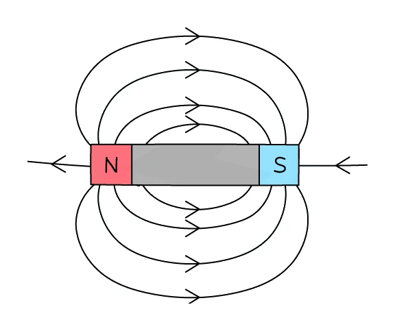
- Field lines always run from N to S outside the magnet (and from S to N inside it, completing a closed loop)
- Field lines never cross or touch each other; they only meet at the poles themselves
The field around a bar magnet
- The field is strongest at the poles, so the lines are packed close together there and spread out further from the magnet
- The pattern is symmetric: lines bow outward from the N pole, curve round, and re-enter the S pole
Common exam question
Drawing the field lines around a bar magnet
Question: Draw the magnetic field lines around a bar magnet to show the shape and direction of the field, add arrowheads to given lines, or circle the mistakes in a drawn pattern (1–3 marks).
Asked in 5 of the 24 papers. A three-mark drawing earns: lines that run from one pole round to the other (a small gap at the magnet is allowed), at least two complete loops that never touch or cross (one scheme asks for four lines, with at least one above and one below the magnet), and arrowheads pointing from N to S. One arrow per line is enough for the direction mark, but a single arrow pointing the wrong way negates it, so check every arrowhead. Lines drawn inside the magnet are ignored rather than penalised.
Asked how the lines show the field weakening with distance, answer with spacing: the lines get further apart, and wider spacing means a weaker field.
Uniform fields
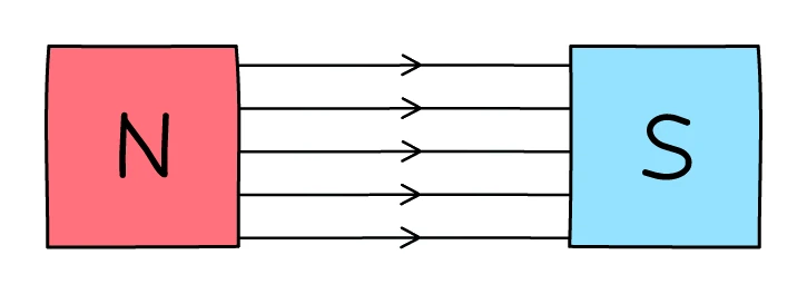
- A uniform magnetic field has the same strength and the same direction at every point. On a diagram it is drawn as a set of equally spaced parallel field lines
- A uniform field can be made by placing two flat magnets with opposite poles facing each other, separated by a few centimetres. Between the poles, the field looks uniform to a good approximation; outside that gap it is curved like a normal two-magnet field
Common exam question
Drawing or describing a uniform magnetic field
Question: Draw the uniform field between two facing poles, explain how a diagram shows that a field is uniform, or describe how to arrange two magnets to produce one (1–3 marks).
Asked in 5 of the 24 papers. The drawing earns its marks for straight, parallel, equally spaced lines running across the gap, plus arrows from N to S (one arrow is enough, but contradictory arrows lose that mark). Explaining why a field is uniform wants two of the same three words: the lines are straight, parallel and evenly spaced. If a pole is unlabelled, label it first: a uniform field only forms between opposite poles facing each other.
To describe the arrangement, give both halves: two magnets with opposite poles facing, and the poles brought close together. A labelled diagram can earn either mark.
3. Permanent and induced magnets
Permanent magnets
- A permanent magnet is made from a magnetically hard material (like steel or a special rare-earth alloy)
- It produces its own magnetic field and keeps doing so even when no other magnet is nearby
- A permanent magnet does not need a current to work
Induced magnets
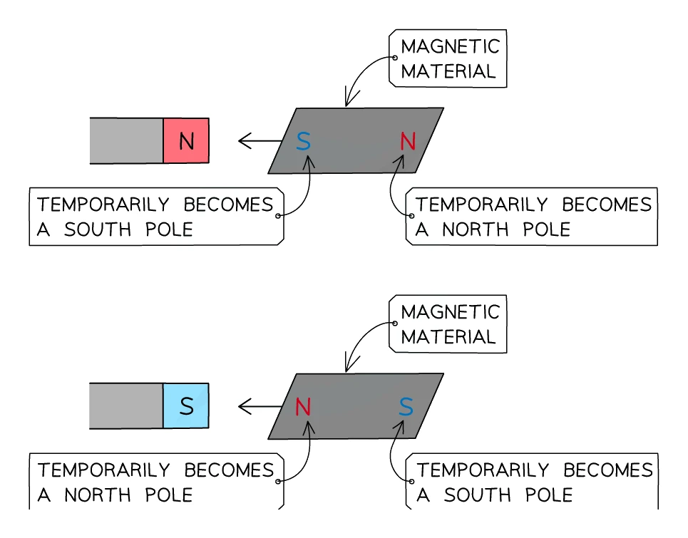
- An induced magnet is a piece of that has been temporarily turned into a magnet by sitting in another magnet's field
- The end of the induced magnet closest to the inducing magnet's pole takes the opposite sign (so the two are attracted)
- The induced magnetism is lost almost as soon as the original magnet is removed, so soft iron releases its magnetism within a fraction of a second
- Induced magnetism is why a paperclip will hang from a bar magnet, and a second paperclip can then hang from the first one, and so on, forming a short chain. Each clip is briefly magnetised by the one above it
Common exam question
Explaining why a piece of iron is pulled towards a magnet
Question: Explain why a piece of iron, or an iron ball, placed in a magnet's field experiences a force towards the magnet (2 marks).
Asked in 2 of the 24 papers. The idea both schemes credit is that the iron becomes magnetised while it sits in the field (one also gives a mark for calling iron a magnetic material), so it is an induced magnet with a pole opposite to the nearby pole on its near side: a north pole faces the magnet's south pole, and opposite poles attract. One scheme accepts the induced pole marked on the diagram, so label N and S on the iron. "The iron is attracted to the magnet" is a mark in one scheme only, and any mention of charge is ignored.
4. Core practical: investigating magnetic fields
Aim
- Use a small plotting compass to map out the magnetic field around (a) a single bar magnet and (b) a pair of bar magnets, and produce labelled diagrams of the field-line patterns
Apparatus
| Equipment | Purpose |
|---|---|
| Two bar magnets | Provide the fields to be mapped |
| Plotting compass (small compass on a clear plastic base) | Reads the direction of the field at each point |
| Sheet of plain A3 paper | Surface to draw the field lines on |
| Sharp pencil and ruler | Marks accurate dots and joins them into smooth curves |
Method
- Lay the bar magnet flat on the centre of the paper. Draw round its outline with the pencil so you can replace it accurately if it gets knocked
- Place the plotting compass near one pole of the magnet (say the N pole) with one end of the needle touching the magnet
- The compass needle aligns with the field at that point. Pencil a small dot at the far end of the needle (the end pointing away from the magnet)
- Slide the compass forwards so the other end of the needle now sits on the dot you just drew. The needle realigns. Pencil a fresh dot at the far end again
- Continue this leapfrog motion until you have a chain of dots that reaches all the way to the S pole of the magnet
- Lift the compass off and join the dots smoothly with a pencil line; this is one field line. Add an arrowhead pointing from N to S
- Repeat steps 2–6 starting from different points around the magnet so you build up about 6–8 field lines in total
- Two-magnet variant: replace the single magnet with two bar magnets laid end-to-end with a 5 cm gap. Do the procedure first with opposite poles facing (you should get smooth lines crossing the gap) and again with like poles facing (you should see a neutral point and lines bending away)
Common exam question
Describing how to plot a magnetic field pattern
Question: Describe an investigation to find the shape of the field around a bar magnet or a current-carrying wire, or name the apparatus that shows the direction of the field lines (1–3 marks).
Asked in 3 of the 24 papers. Two methods are credited; for a bar magnet a labelled diagram can earn every mark. With a plotting compass: dot the far end of the needle, move the compass on and repeat, then join the dots into a continuous line (one mark each for the compass, for moving it or using several, and for joining the dots). With iron filings: sprinkle them on a card over the magnet or around the wire and tap the card so they line up; "poured" is ignored. Only the compass gives the direction of the lines, so it is the apparatus to name. For the wire, using magnets or a second wire earns nothing; the right-hand grip rule alone is condoned for one mark.
Sources of error and safety
- Random error: read the compass needle from directly above so it isn't viewed at a slanted angle; let the needle settle for a couple of seconds before marking each dot; keep iron objects (scissors, pencils with steel ferrules) away from the apparatus so they don't deflect the compass
- Systematic error: avoid using a magnetised steel pencil-tip near the compass; use a sharp graphite pencil for the markings only
- Safety: this is a low-risk practical with no hot or electrical equipment; the only precaution is to keep the magnets away from pacemakers, credit cards and computer hard drives
5. Magnetic field around a current-carrying conductor
Around a straight wire
- A current flowing in a straight wire produces a in the space around the wire
- The field forms concentric circles around the wire, lying in planes perpendicular to the wire
- Key features:
- the field has no poles, because it is a circular field, not a dipole field
- the field is strongest close to the wire (lines packed densely) and weaker far away (lines spread out)
- increasing the current makes the field stronger; reducing it weakens it
- reversing the current direction reverses the direction of the field circles
The right-hand thumb rule
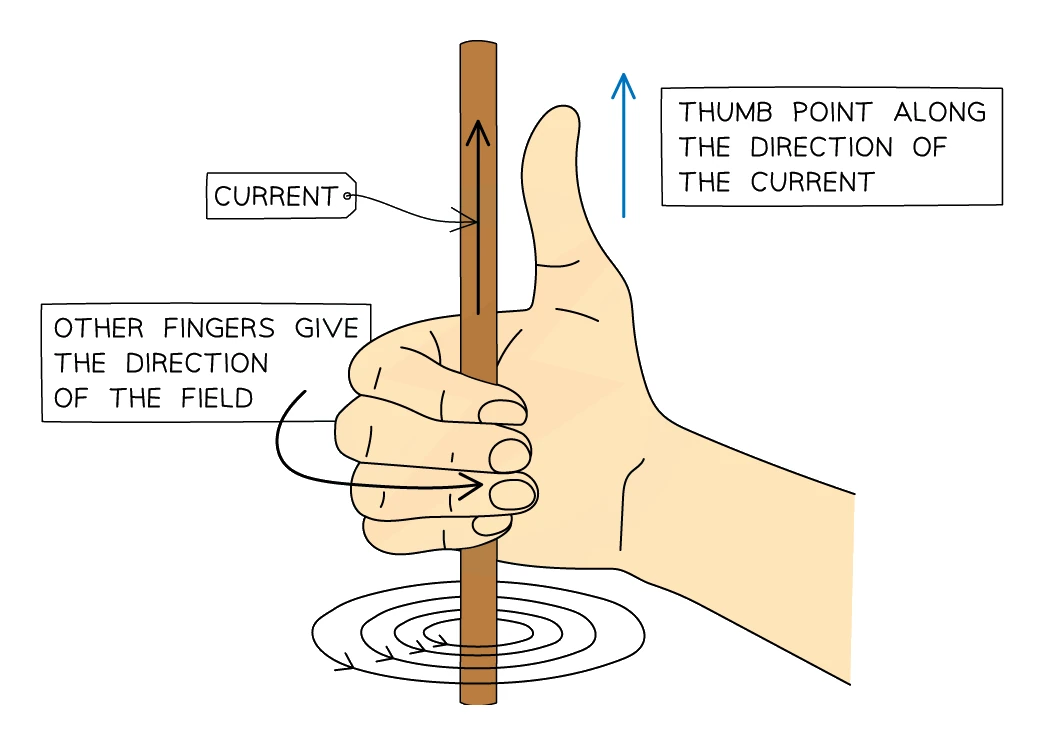
- The direction of the field around a current-carrying wire is given by the right-hand thumb rule:
- Make a thumbs-up gesture with your right hand
- Thumb points in the direction of the conventional current in the wire
- Curl of the fingers shows the direction of the circling round the wire
Common exam question
Why a current-carrying wire has a magnetic field
Question: Explain why there is a magnetic field around a wire or coil, or why a compass needle moves when a current is switched on, or draw the field around a straight wire (1–3 marks).
Asked in 5 of the 24 papers. Every scheme wants the idea that the current in the wire produces a magnetic field; saying the wire "becomes magnetic" is ignored. Explaining the field's direction needs the current's direction (moving charge or electrons count, but electrons flow the opposite way; "positive electrons" rejected). A compass needle is a magnet, so it lines up along a field line. Reversing the current reverses the direction of the field.
For the drawing, the lines are circles centred on the wire, at right angles to it: one mark for a single centred circle, one for at least two concentric circles, one for an arrowhead in the correct sense (clockwise when the current flows away from you); contradictory arrows are rejected.
In a flat coil
- A single loop of wire concentrates the field through the centre of the loop. On one face of the loop the field comes out (north-like); on the other face it goes in (south-like)
In a solenoid
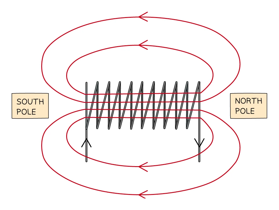
- A solenoid is a long coil with many turns of wire stacked along its length
- Inside the solenoid the individual loops' fields add up to give a strong, almost uniform field along the axis, just like the field inside a bar magnet
- Outside the solenoid, the field comes out of one end and curls round to re-enter the other end, exactly like the field around a bar magnet, with one end behaving as a north pole and the other as a south pole
- To work out which end is which, look at it end-on:
- if the current is travelling anticlockwise when you look at that end, that end is the north pole
- if the current is travelling clockwise when you look at that end, that end is the south pole
- Increasing any of the following makes the solenoid's field stronger:
- the current in the wire
- the number of turns per unit length of the coil
- placing a soft iron core inside the coil (the iron becomes an induced magnet and adds its own field on top)
Exam tip
Describing the construction of an electromagnet
A three-mark description of an electromagnet needs three things, each of which may be shown on a labelled diagram: a coil (solenoid) of wire with many turns, a direct current in it (a battery or power pack in the circuit is condoned), and a soft iron core inside the coil. The scheme accepts "a magnetically soft material" for the core but ignores steel, so a steel core earns nothing. It rejects a core drawn as a complete iron loop round the coil and any mention of a bar magnet, and ignores a.c., so make the current d.c.
6. The motor effect and Fleming's left-hand rule
The motor effect
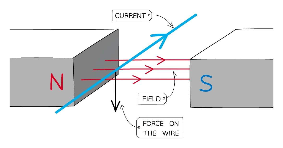
- A current-carrying wire placed in a experiences a force
- This is the motor effect: the field of the magnets and the field around the current-carrying wire interact, and the resulting force pushes the wire sideways out of the field
- Three requirements for there to be a force:
- there must be a current flowing in the wire
- the wire must be in a magnetic field
- the wire must lie at an angle to the field. The force is largest when the wire is at 90° to the field, and zero when the wire is parallel to the field
Fleming's left-hand rule
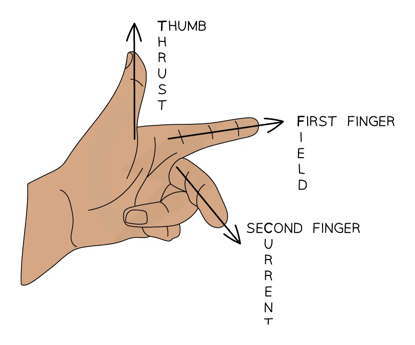
- The directions of the three quantities (current, field and force) are mutually perpendicular. To work out which way the force pushes the wire, use Fleming's left-hand rule:
- First finger → direction of the magnetic Field (N to S)
- seCond finger → direction of the conventional Current (+ to −)
- THumb → direction of the THrust (the force on the wire)
- Hold your left hand with the three digits all at right angles to one another like the corner of a box. Rotate your hand until the first finger lines up with the field and the second finger lines up with the current, and the thumb then automatically points along the force
Common exam question
Finding the direction of the force on a wire
Question: Draw an arrow for the direction of the force on a current-carrying wire between two poles, or pick which side of a coil moves upwards (1–2 marks).
Asked in 4 of the 24 papers. Use your left hand: first finger along the field from N to S, second along the conventional current, thumb along the force. The two marks are split: one for an arrow along the correct line (at right angles to both field and current) and one for the correct sense along it, so the right line alone still earns the first. Where the arrow starts is ignored, as are any field lines you add.
In a cross-section the current is a dot (out of the page) or a cross (into it): point your second finger out of or into the paper first. A follow-up may ask for changes that reduce the force: a weaker field (weaker magnets, or magnets further apart) or a smaller current.
Factors that change the size of the force
- The force on a current-carrying wire in a magnetic field is larger when:
- the current is bigger (more charge per second crossing the field)
- the magnetic field is stronger (use a stronger magnet)
- the angle between the wire and the field is closer to 90° (90° gives maximum; parallel gives zero)
- in extended geometry, the length of wire inside the field is longer
The d.c. motor (a practical application)
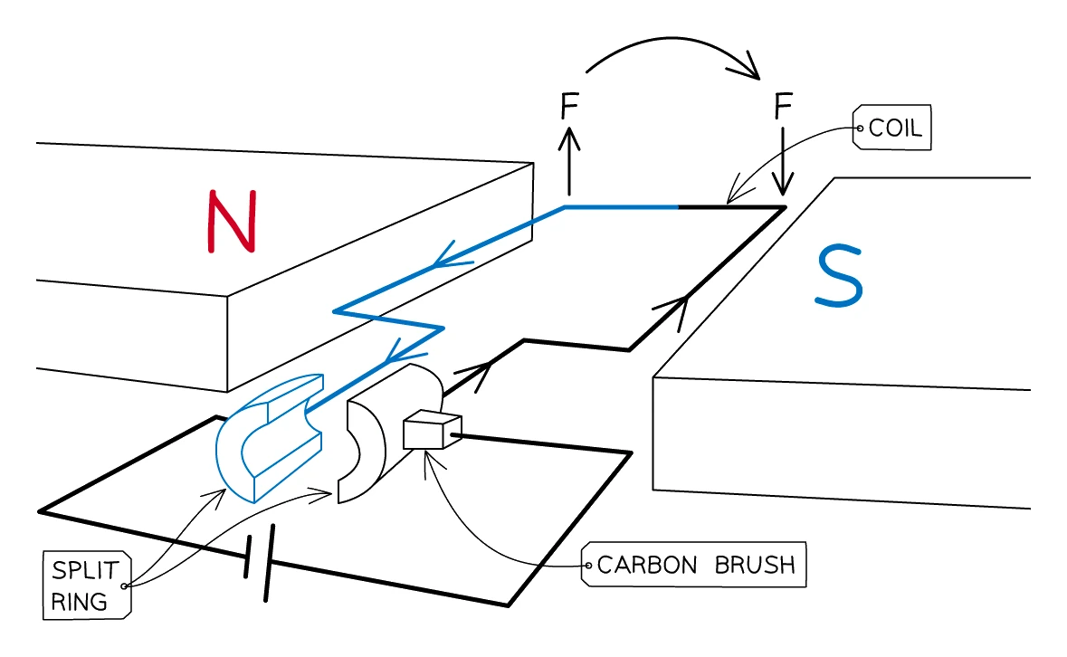
- A simple d.c. motor uses the motor effect to spin a coil of wire continuously between the poles of two magnets:
- The coil is wired into a circuit through a split-ring commutator at one end. The two halves of the split ring are pressed against two carbon brushes that feed current in
- With the coil horizontal, current flows one way along the front side of the coil and the opposite way along the back side. Each side sits in the same magnetic field, but their currents are opposite, so Fleming's left-hand rule predicts opposite forces: one side is pushed up, the other pushed down. The coil starts to rotate
- When the coil has rotated a quarter turn (vertical), the two halves of the split ring lose contact with the brushes, no current flows, and no force acts; the coil's own momentum carries it past the vertical
- As the coil continues past the vertical, the split-ring swap means that the side now on the right is connected to the same brush as the side that was previously on the right, so the current in each side of the coil reverses relative to the magnets. The forces remain pushing each side the same way they were before, and the coil keeps rotating in the same sense
- The motor's speed can be increased by increasing the current, or by using a stronger magnet, or by adding more turns to the coil
- The direction of rotation can be reversed by reversing the current or by swapping the magnets round
- A loudspeaker runs on the same physics in miniature: an alternating current flows through a small coil sitting in a permanent magnet's field. The coil oscillates back and forth in step with the current, pushing a paper cone that vibrates the air and produces a sound wave
Common exam question
Explaining why a motor coil starts to turn
Question: Explain why a motor coil starts to rotate when a current flows, and sometimes why a loop with no commutator stops once it is vertical (4 marks).
Asked in 2 of the 24 papers. Give a chain of four points: the current in the coil produces a magnetic field; this field interacts with the magnet's field; so there is a force on each side of the coil; and the forces on the two sides are in opposite directions, because the currents in them flow opposite ways. "Attraction and repulsion" and "cutting field lines" are ignored, so write about interacting fields and forces. An upward force on one side and a downward force on the other earns the opposite-forces point.
For the loop that stops when vertical, any three of those plus one more earn the marks: the forces do not change direction (no turning effect when vertical) because the current cannot swap direction without a split-ring commutator.
Common exam question
Describing how a loudspeaker produces sound
Question: Describe or explain how an alternating current in the coil of a loudspeaker produces a sound (4 marks).
Asked in 2 of the 24 papers. Each scheme awards any four links from its own list, and between them they credit this chain: there is an alternating current in the coil; the current gives the coil a magnetic field; this field interacts with the permanent magnet's field; so there is a force on the coil and the cone attached to it; because the current alternates, the force keeps changing direction; so the cone vibrates, making the air vibrate and sending out a longitudinal wave. Only four links are on both lists (the fields interacting, the force, the force changing direction and the cone vibrating), so never leave one of those out. "Fields cutting" and any reference to induction earn nothing: this is the motor effect, not a generator.
7. Magnetic force on a moving charge
The force on a free charge
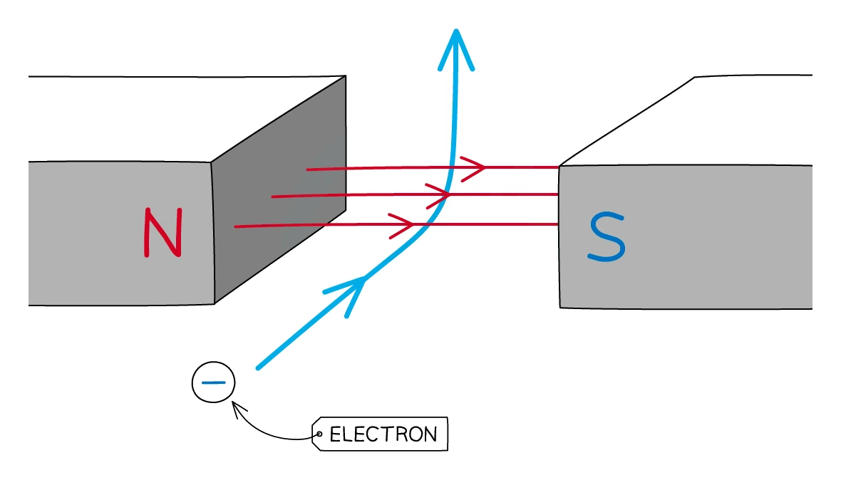
- The motor effect doesn't need a wire, because it works on any moving charged particle in a magnetic field. The wire is just a convenient way to keep many charged particles moving in a line
- A single moving charge in a magnetic field feels a force at right angles to both its direction of motion and the field
- The direction of the force is given by Fleming's left-hand rule, with the following adjustment for an electron (or any negative charge):
- conventional current flows in the opposite direction to electron motion
- so to find the force on an electron, point the second finger opposite to the electron's motion (i.e. in the conventional-current direction)
- The size of the force depends on the speed of the charge, the strength of the field, the size of the charge, and the angle between the velocity and the field:
- maximum force when the charge moves perpendicular to the field
- zero force when the charge moves parallel to the field
- intermediate angles give a force somewhere between
Common exam question
The force on a charge moving through a magnetic field
Question: A proton moves through a uniform magnetic field: find the direction of the force (or of the field), explain how the force changes as it moves, and suggest why its velocity changes (1–4 marks).
Asked in 2 of the 24 papers, both on Paper 2. For the direction, treat the moving positive charge as a conventional current and use the left-hand rule as for a wire; the force, the velocity and the field are all at right angles to one another, so any option that puts two of them along the same line is wrong. For how the force changes, any two score: the force is always at right angles to the velocity; it changes the particle's direction; the motion is equivalent to a current, so as the motion turns the direction of the force changes too; and the magnitude of the force stays constant. The velocity changes because its direction changes; "the speed changes" is ignored.
Curving paths in a magnetic field
- Because the force is always at right angles to the velocity, a charge moving perpendicular to a uniform magnetic field travels in a circle. The field changes the direction of motion but never its speed (the force does no work, since it is always at 90° to the displacement)
- This is the basis of the electron-beam deflection in old cathode-ray tube televisions, and of particle accelerators (cyclotrons, synchrotrons) where charged particles are steered around a circular path by powerful magnets
- Earth's magnetic field deflects high-speed cosmic-ray particles in much the same way, which is part of why life on the surface is shielded from much of the radiation arriving from space