1. Electromagnetic induction
The generator effect
- Electromagnetic induction is the production of a voltage (and hence a current, if there is a complete circuit) in a conductor whenever the conductor experiences a changing magnetic field
- This is sometimes called the . It is the reverse of the motor effect:
- For the , a current must already be running in the conductor; the magnetic field then pushes the wire sideways
- For the generator effect, no current is needed to start with; the voltage appears spontaneously when the conductor cuts through magnetic field lines
Two ways to get a changing field
There are two equally good ways to set up the changing field that produces induction. The physics is the same in both:
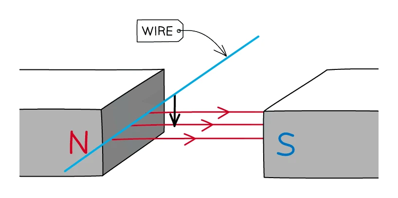
- Move a conductor through a stationary magnetic field. A wire pushed between the poles of a magnet sweeps through the field lines and a voltage is induced along its length
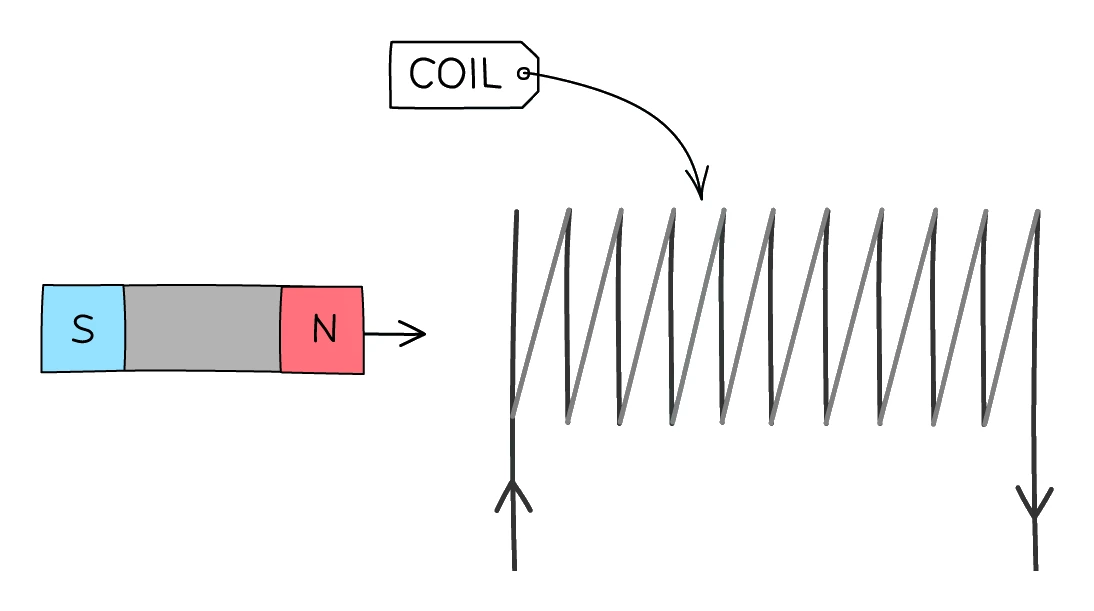
- Move a magnet relative to a stationary conductor. A bar magnet pushed in and out of a coil of wire makes the magnetic field inside the coil change, inducing a voltage across the ends of the coil
Common exam question
Explaining why a voltage is induced in a moving wire
Question: Explain why a voltage is induced, or a current produced, when a wire moves through a magnetic field, a magnet moves near a loop, or a conductor sits in a changing field (1–3 marks).
All but one scheme gives a mark for the conductor cutting the magnetic field lines: "passes through" is accepted, "interacts with" is ignored by two schemes. For more marks, continue the chain: the cutting induces a voltage (p.d. accepted), and a complete circuit lets it drive a current. Asked in 6 of the 24 papers.
When the field changes instead (a metal detector's coil, a transformer core), say the field through the conductor is changing, then that field lines are cut and a voltage is induced ("a current is induced" is ignored there); for a solid core, the further marks are for free electrons being pushed along as the current. Asked which way to move the wire: up and down, across the field lines.
Factors that change the size of the induced p.d.
- The induced voltage gets bigger when:
- the speed of relative motion between magnet and coil is faster (faster sweep through the field lines means more field lines cut per second)
- the number of turns on the coil is larger (every turn picks up its own contribution; they add together)
- the strength of the magnet is greater (a stronger field means more field lines for the same volume, so more get cut per second)
- the cross-sectional area of the coil is larger (more wire is moving through the field)
Common exam question
Changes that make the induced voltage bigger or smaller
Question: State two changes that would increase the induced voltage, predict or explain the reading when the wire is moved faster, or suggest how a generator's output could be reduced (1–4 marks).
For a wire between magnets, credit goes to: move it faster, use stronger magnets, bring the magnets closer together, or wind the wire into a coil. "Bigger magnets" is ignored, and so is "more turns on the coil" while the conductor is a single wire. For a generator, fewer coils or turns, weaker magnets and slower rotation all count as ways to reduce the output. Asked in 6 of the 24 papers.
An "explain" version wants the chain: moving faster means more field lines are cut per second, giving a larger induced voltage and so a larger current (moved to and fro, it also alternates faster). A one-mark "why might it change" takes a change of speed or a non-uniform field.
Factors that change the direction of the induced p.d.
- The induced voltage reverses direction when:
- the direction of motion is reversed (pulling out instead of pushing in)
- the magnet is flipped (N pole leading instead of S)
- Both of these "flip" the way field lines are being cut, and so flip the polarity of the induced p.d. The size of the p.d. is not affected; only its sign
Common exam question
Why the induced voltage changes sign
Question: Explain why the sign of the voltmeter reading changes as a conductor moves backwards and forwards through a field, or predict the current when the poles of the magnet are reversed (1–3 marks).
The three-mark explanation is a chain: the conductor changes direction; the direction of the induced voltage depends on the direction of relative motion; so the voltage reverses, and the sign of the reading follows it. A further credited point is that at the ends of each stroke the conductor is momentarily still, so the voltage is zero. Speed is irrelevant to the sign and earns nothing here, though "current" is condoned for "voltage". Asked in 3 of the 24 papers.
Reversing the poles of the magnet gives a reading of the same size with the opposite sign. A wire moved up and down repeatedly gives a reading that swings negative, an alternating current, because the wire keeps changing direction.
Exam-language reminders
- Use "add more turns to the coil", not "add more coils". A coil is the whole component, and the loops in it are turns
- Use "a stronger magnet", not "a bigger magnet". Magnet size and magnet strength are not the same thing
- Always say the conductor must cut magnetic field lines to induce a p.d. If the wire is moved parallel to the field, no lines are cut and no voltage is induced
2. Generators and dynamos
The generator effect put to work
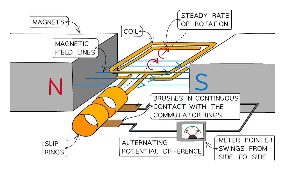
- A continuous voltage can be produced by rotating a coil of wire in a magnetic field: as the coil spins, the two long sides sweep through the field at every angle in turn, inducing a constantly changing voltage
- The same physics powers two related devices that differ only in how they connect the rotating coil to the external circuit:
- The (alternator) uses slip rings and produces an
- The (dynamo) uses a and produces a that pulses but never reverses
The a.c. generator (alternator)
- A rectangular wire loop is driven round and round inside a uniform magnetic field by some external mechanical input (a steam turbine, a wind turbine, or the pedals of a bicycle dynamo)
- The two ends of the coil are connected to two separate slip rings, which are full circular metal bands attached to the coil's shaft, one at each end. The rings stay in continuous contact with two carbon brushes that feed the induced current out to the external circuit
- Because the slip rings are full rings (no breaks), the same end of the coil is always connected to the same terminal of the external circuit. Whichever way the current is going inside the coil is mirrored straight out to the load
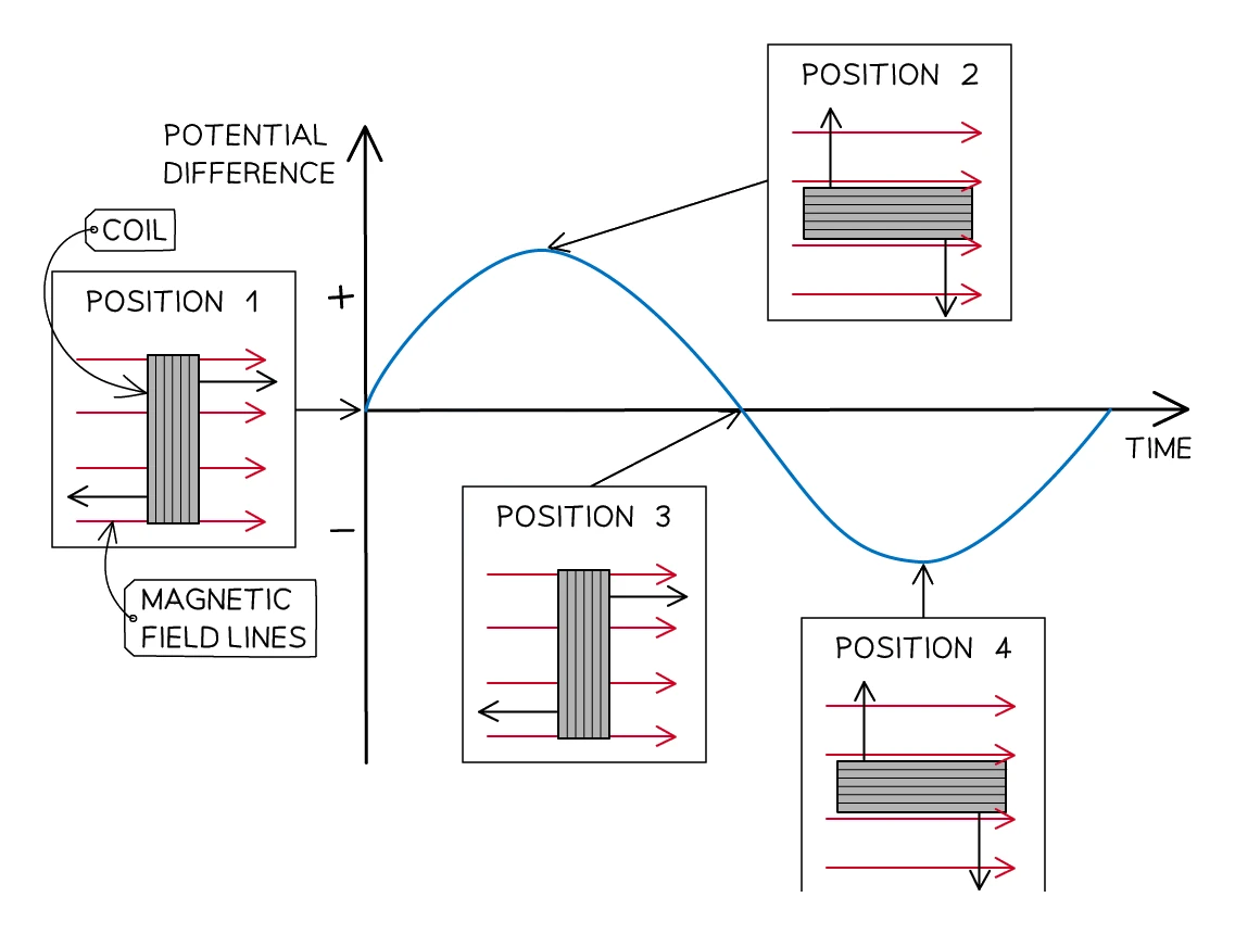
- As the coil spins:
- When the coil's flat face is parallel to the field, the long sides are slicing through the field as fast as possible, so induced p.d. is at its maximum
- A quarter turn later, the coil is perpendicular to the field and the long sides momentarily move parallel to the field. No lines are being cut, so induced p.d. is zero
- Another quarter turn flips the direction of the cutting motion, so induced p.d. is at its maximum but now in the opposite polarity
- The cycle repeats every full revolution, giving a sinusoidal alternating voltage
The d.c. generator (dynamo)
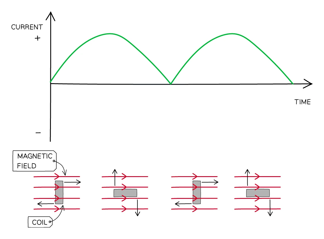
- The mechanical layout is identical to the alternator's, but the slip rings are replaced by a split-ring commutator, which is a single ring of metal cut into two semicircular halves, each connected to one end of the coil and pressed against a fixed brush
- Every half turn of the coil, the two halves of the split ring swap which brush they touch. This swap happens at exactly the moment the induced p.d. is reversing inside the coil, so the polarity reaching the external circuit stays the same instead of flipping
- The result on the external circuit is a pulsing direct current: the voltage rises from zero to a peak and falls back to zero, then rises to a peak in the same direction again, then back to zero, and so on. The output is always positive (or always negative), never alternating
- A bicycle dynamo is the everyday example; older cars used dynamos for the same reason, before switching to alternators
Common exam question
Explaining how a generator produces a current
Question: Explain how a generator (a coil turning between magnets in a wind turbine or a power station) produces a current or generates electricity (2–3 marks).
Three ideas carry the marks: the coil rotates in the magnetic field (a rotating magnet is accepted instead), the coil cuts the magnetic field lines (a coil experiencing a changing flux is accepted), and a voltage is induced (p.d. accepted). Asked in 2 of the 24 papers.
Two slips cost marks. "The magnetic fields interact" is motor-effect language and is ignored here: the coil cuts the field. And write that a voltage is induced rather than a current: one scheme allows "a current is induced" and the other ignores it, so voltage is the safe word.
3. Transformers
What a transformer does
- A transformer is a device that takes an alternating voltage in and produces a different alternating voltage out, all on the same frequency
- A transformer only works with . A direct current produces a steady magnetic field that doesn't change, so no voltage is induced in the secondary
Exam tip
Why a transformer does not work with direct current
Set once as a three-mark question of its own, and a marking point in every "explain how a transformer works" answer. Give the mechanism in three steps: a constant current produces a constant magnetic field in the core; induction needs a changing field (field lines being cut is accepted); so no voltage is induced in the secondary coil. "Transformers need a.c." only repeats the question and is ignored, as is "it works with a.c." in the longer explanation. "No current is induced" is condoned, but voltage is the credited word, and "flux" or "field lines" is accepted for the field.
Structure
A basic transformer has three parts:
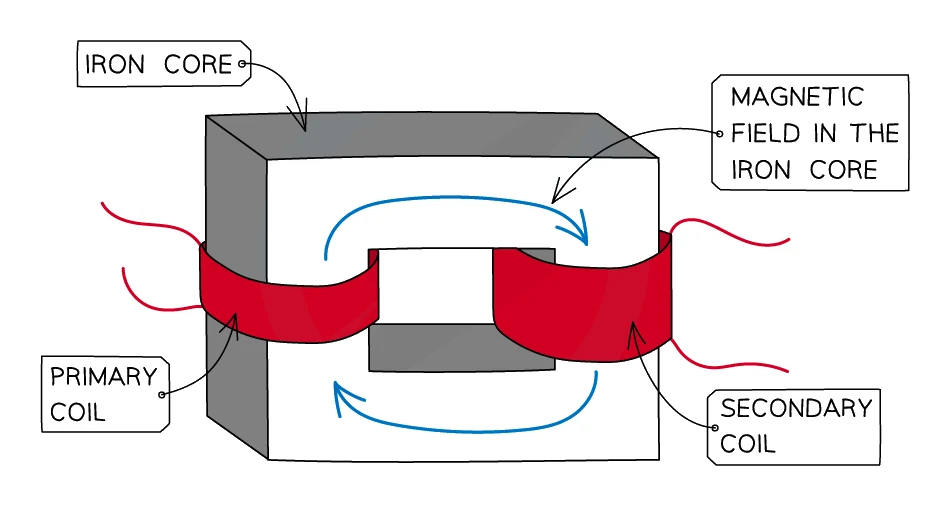
- A primary coil of insulated wire wound around one limb of a soft iron core. The input alternating current goes through this coil
- A secondary coil of insulated wire wound around a different limb of the same iron core. The output is taken from this coil
- A laminated soft-iron core that links the two coils magnetically without letting them touch electrically. Soft iron is used because it magnetises and demagnetises quickly, faithfully tracking the rapidly changing magnetic field
How it works, step by step
- An in the primary coil sets up a continuously changing magnetic field around the primary
- The iron core channels this changing magnetic field round to the secondary coil, because soft iron concentrates the field very efficiently
- The secondary coil now sits in a continuously changing magnetic field, so a voltage is induced in it by electromagnetic induction
- The induced voltage in the secondary is alternating at the same frequency as the primary current; only the size of the voltage is different
- If the secondary is connected to a complete circuit, an alternating current flows through the load
Common exam question
Explaining how a transformer works
Question: Explain how a (step-down) transformer works, giving reasons for the two coils, the iron core and the a.c. supply (4–6 marks).
Set in 2 of the 24 papers, both on Paper 2. Any four or six of these score, so give the chain in order: the transformer steps the voltage up or down (step-down: fewer turns on the secondary); the current in the primary coil produces a magnetic field; that current is alternating, so the field is changing; the changing field is set up in the core (magnetising and demagnetising it); the core strengthens or concentrates the field and links the two coils (iron is magnetically soft: it gains and loses magnetism easily); the field lines cut the secondary coil; which induces a voltage in it (current condoned); and it will not work with steady d.c.
"Input" and "output" are accepted for primary and secondary; "it works with a.c." only repeats the question and is ignored.
Step-up and step-down
- A step-up raises the voltage. It has more turns on the secondary than on the primary (Ns > Np)
- A step-down transformer lowers the voltage. It has fewer turns on the secondary than on the primary (Ns < Np)
- The current behaves in the opposite way: a step-up transformer reduces the current; a step-down transformer increases it. This is required by conservation of energy (see the power equation in section 4)
Transformers and the National Grid
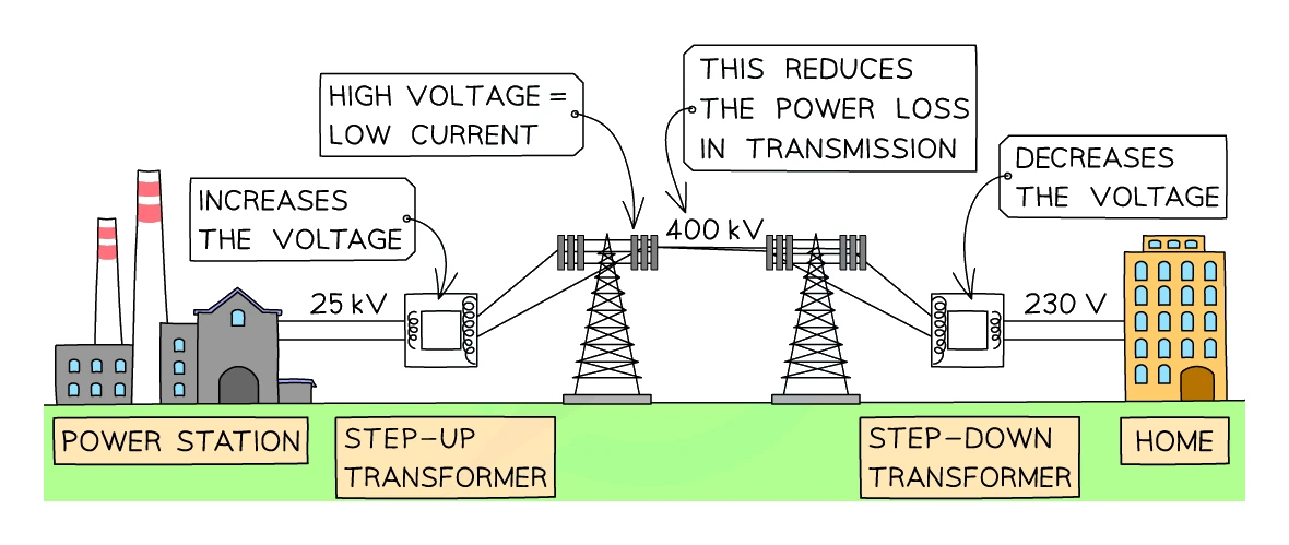
- The UK National Grid uses transformers to move electricity efficiently from distant power stations to homes:
- At the power station, a step-up transformer raises the voltage to 400 kV for long-distance transmission
- Pylons carry this high-voltage, low-current electricity across the country
- Local substations use step-down transformers to drop the voltage back to 230 V before the supply enters homes and businesses
- Why bother stepping up at all? Energy loss in the transmission cables comes from the heating effect of the current (I²R loss). Sending the same total power at a higher voltage means a lower current, and the heating loss falls dramatically. A cable carrying 1 GW at 400 kV runs at 2500 A; the same 1 GW at 25 kV would need 40 000 A and the cable would melt
- Additional bonus: lower currents mean thinner, cheaper cables can carry the load
Common exam question
Why step-up and step-down transformers are used
Question: Explain why the National Grid is fed through a step-up transformer, or why a transmission line has a step-up transformer at the power station and a step-down transformer at the town (2–4 marks).
The two-mark core: stepping up the voltage reduces the current, and a lower current means less heating in the cables, so less energy or power is wasted. Give that second half: "it is more efficient" on its own, with no reason, is ignored. Asked in 2 of the 24 papers, both on Paper 2.
The four-mark version adds a mark for stating that the step-up transformer increases the voltage (or the step-down one decreases it) and a mark for why the town needs the step-down: homes need a low voltage for safety, or so that appliances work correctly. Keep voltage and current straight: it is the voltage that is raised and the current that falls, never both.
4. Transformer equations
Voltage-and-turns ratio
For an ideal transformer, the voltage on each side of the iron core is proportional to the number of turns on that side:
Vp / Vs = Np / Ns
- where:
- Vp = voltage across the primary coil (V)
- Vs = voltage across the secondary coil (V)
- Np = number of turns on the primary coil
- Ns = number of turns on the secondary coil
- The equation can equally be written upside down (Vs / Vp = Ns / Np). Pick the form that puts the unknown on the top of a fraction so you have less rearranging to do
- The key fact: the ratio of voltages equals the ratio of turns
Common exam question
Stating the transformer equation and finding the turns
Question: State the formula linking input voltage, output voltage and turns ratio, then calculate the turns on the secondary coil (1 mark, then 3 marks).
The formula mark takes Vp/Vs = Np/Ns in any rearrangement or in words; input/output for primary/secondary, T or n for turns, even "coils" for "turns", are allowed, but the words "turns ratio" in place of the two turn numbers are rejected. Asked in 3 of the 24 papers, all on Paper 2.
The calculation gives one mark each for substitution, rearrangement and evaluation; a bare correct answer earns all three. A power-of-ten slip (kV) loses a mark, and the answer needs at least 2 significant figures, rounded not truncated: a truncated whole number lost the final mark in one paper. One paper also asked how to change the primary coil to raise the output voltage: fewer turns on the primary; answers about the secondary, or about raising the primary's current, power or voltage, are ignored.
Worked example
Transformer equation: finding the number of turns
A step-up transformer has a primary voltage of 25 V and 200 turns on the primary coil. The secondary voltage is 100 V. Calculate how many turns the secondary coil must have.
Solution:
- Write the transformer equation: Vp / Vs = Np / Ns
- Rearrange for Ns: Ns = Np × (Vs / Vp)
- Substitute: Ns = 200 × (100 / 25)
- Ns = 200 × 4 = 800 turns
Conservation of energy
- An ideal transformer is 100 % efficient, with no energy lost as heat in the coils, the core, or eddy currents
- Real transformers reach about 99 % efficiency; the small loss appears as gentle warming of the iron core
- For an ideal transformer, the input electrical power equals the output electrical power:
Vp × Ip = Vs × Is
- where:
- Ip = current in the primary coil (A)
- Is = current in the secondary coil (A)
- This is just the statement P = V × I applied to both sides of the transformer
- A direct consequence: if the voltage is stepped up by some factor n, the current is stepped down by the same factor n, and vice versa
Common exam question
Using input power = output power on a charger label
Question: From a charger label giving input and output voltages and currents, explain how it shows a step-down transformer, show it is approximately 100 % efficient, or calculate the input current assuming 100 % efficiency (2–3 marks).
Step-down from the label is two marks: the output voltage is lower than the input voltage, and the output current is higher than the input current. Set in 2 of the 24 papers, both on Paper 2.
Showing it is about 100 % efficient is three marks: any attempt at a power (voltage × current), one power correct, and a statement that the two powers are about equal, or an efficiency worked out as about 100 %. For the input current, find the output power first (output voltage × output current), equate the input power to it and divide by the input voltage; substitution, rearrangement and evaluation earn one mark each, with ECF from a wrong output power.
Worked example
Input current of a step-down transformer
A step-down transformer in a garden-light supply takes 230 V from the mains and delivers 12 V at 2.5 A to the lamps. Assuming the transformer is 100 % efficient, calculate the current in the primary coil.
Solution:
- Output power = Vs × Is = 12 × 2.5 = 30 W
- For 100 % efficiency, input power = output power, so Vp × Ip = 30 W
- Ip = 30 ÷ 230 = 0.1304… A
- Input current = 0.13 A
The high-voltage side carries the smaller current: if a step-down transformer's input current comes out larger than its output current, the division is the wrong way round.