1. Current in series and parallel
Series circuits
- A series circuit is a circuit in which every component sits on the single loop that the current must travel around
- The same current flows through every component because there is only one path for the charge to take; what enters one end of the loop must come out of the other
- A break anywhere in a series circuit (a blown bulb, a loose wire, an open switch) stops the current everywhere, because there is no alternative route
Current in a series circuit is the same at every point
- An ammeter placed anywhere in a series circuit reads the same value
- The current is set by:
- the total voltage of the supply (cell or battery)
- the total resistance of all the components added together
- Increasing the supply voltage pushes more current around the loop; adding more components in series raises the total resistance and so reduces the current
Parallel circuits
- A contains two or more loops that the current can take, joined at points called
- The wires connecting two junctions are called branches; each branch carries its own share of the current
- Because each branch is independent, a break in one branch leaves the other branches still working, since only the branch with the fault loses its current
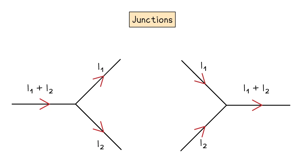
Current splits at junctions: conservation of charge
- At any junction, whatever current arrives must also depart, so the sum of branch currents in equals the sum of branch currents out
- This is a direct consequence of conservation of charge: charge can be neither created nor destroyed, so whatever flows in must flow out
- The split between branches is not necessarily equal, because branches with lower resistance carry more current and branches with higher resistance carry less. The two are only equal when the branches have identical resistance
Common exam question
Finding currents at a junction in a parallel circuit
Question: Calculate the current in the battery (or the supply) of a parallel circuit from the branch currents shown, or find a missing branch current (1–2 marks).
The supply current is the sum of the currents in the branches that are switched on, and a missing branch current is the supply current minus the other branches. Set in 4 of the 24 papers. Where there are two marks, one is for showing the addition and one for the value; one scheme accepts the answer in amps as well as in milliamps, so convert only when the question names a unit.
Read the switches before you add: in one paper a branch whose switch was open had to be left out, and adding all three currents earned one mark of the two. The current in the wire returning to the battery equals the current leaving it, so a label on the return wire is just the supply current.
2. Voltage in series and parallel
Voltage in series
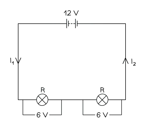
- The total voltage of the supply is shared between the components in a series loop:
V_supply = V₁ + V₂ + V₃ + …
- The share that each component takes is set by its resistance:
- Two identical components in series each take half the supply voltage
- A component with higher resistance takes the larger share of the supply voltage
- A component with lower resistance takes the smaller share
- This is why a high-resistance bulb in series with a low-resistance wire glows brightly while the wire stays cool: the bulb is dissipating most of the supply's energy because most of the voltage is dropped across it
Common exam question
Voltage across one component in a series circuit
Question: Calculate the voltage across one component in a series circuit from the supply voltage and the voltage across the other component, or explain how it changes when a resistance changes (2–4 marks).
The supply voltage is shared, so the voltage across the component is the supply voltage minus the voltage across the other component: in the two-mark version that idea is the first mark and the subtraction the second. Set in 4 of the 24 papers. When the question goes on to V = IR, use the component's own voltage: a current from the full cell voltage scored at most two marks of four. Run backwards, the supply voltage is the sum of the two component voltages.
For the explain version, write the chain: the component's resistance rises, so the total resistance rises and the current falls; the voltage across the fixed resistor falls, so the voltage across the changed component rises, because the total voltage is constant.
Voltage on parallel branches
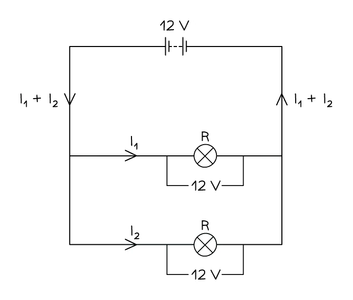
- Every parallel branch sits between the same two junction points; the voltage across one branch therefore matches the voltage across any other branch, and both equal the supply voltage:
V_supply = V_branch1 = V_branch2 = …
- This is because the two ends of every branch are joined to the same two points (the two junctions), and the potential difference between two fixed points is one number whatever route you take between them
- A consequence: any single branch in a parallel circuit will run at its normal "rated" voltage if it is rated to match the supply; this is why household appliances are wired in parallel
Common exam question
Voltage across a parallel branch
Question: State the voltage across one component in a parallel circuit, or explain how it compares with the voltage across the cell (1–2 marks).
Every branch sits across the full supply voltage, so the voltage across the component equals the cell voltage: give the number. In the two-mark version the second mark is for the reason, that the components are in parallel. Set in 2 of the 24 papers. Once you have calculated the voltage across one of two parallel resistors, the voltage across the other is the same value, and a slip in the first part is carried forward.
Never write that the cell's voltage is shared between the branches: sharing is the series rule, and one scheme rejects it outright. The same fact is credited elsewhere: every lamp gets the full voltage when you explain parallel lighting, and every lamp has the same voltage when you explain which lamp is brightest.
Advantages and disadvantages of each wiring
| Feature | Series circuit | Parallel circuit |
|---|---|---|
| Controlling all components together | Yes, one switch acts on every component | Possible, but each branch usually has its own switch as well |
| Controlling components separately | No, they share one current path | Yes, each branch has its own switch |
| Effect of one broken component | All others stop working | Only that branch stops; the others carry on |
| Wiring complexity | Simple, fewer wires needed | More complex, more wires and junctions |
| Voltage across each component | Shares the supply voltage; depends on resistance | Each branch gets the full supply voltage |
Common exam question
Advantages of parallel or series wiring
Question: Explain an advantage of using a parallel circuit for domestic lighting, or give an advantage and a disadvantage of connecting bulbs in series (1–2 marks).
For parallel lighting, one mark is for the advantage and one for linking it to the circuit. Advantages credited: the lamps can be switched on and off independently, if one lamp fails the rest stay lit, and every lamp gets the full mains voltage. The link is that it is a parallel circuit, with the lamps on separate branches; a bare advantage with no mention of parallel branches loses the second mark. Set in 2 of the 24 papers.
For bulbs in series, the disadvantage is that if one bulb fails they all go off, or that they cannot be controlled individually. Accepted advantages: a simpler circuit with fewer wires, one switch controls them all, each bulb needs only a lower voltage, and the circuit is less likely to overheat.
3. Resistors in series
Adding resistors in series
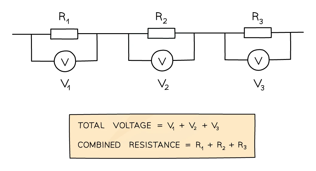
- Place several resistors one after the other on the same loop and their total resistance is found by adding the individual resistances together:
R_total = R₁ + R₂ + R₃ + …
- Adding another resistor in series makes the loop harder for charge to flow through, so the total current falls (for a fixed supply voltage)
- The total voltage from the supply is shared across the resistors in the same ratio as their resistances: a bigger resistor takes a bigger fraction of the voltage
Quick rules to recall
- For components in series:
- current is the same at every point in the loop
- the supply voltage is shared between components, in proportion to their resistances
- the total resistance is the sum of the individual resistances
- For components in parallel:
- the supply current splits between the branches and recombines at junctions
- every branch carries the full supply voltage
- the total resistance is less than the smallest individual branch resistance (a second branch always offers an extra path for charge, lowering overall resistance)
Common exam question
How the current changes when a circuit is rewired
Question: Explain how the current in the battery (or the ammeter reading) changes when a second branch is added in parallel, or when the components are reconnected in series instead (3–5 marks).
Every link in the chain is a mark. A new branch gives the charge an extra path, so the total resistance falls; the battery voltage is unchanged; so the battery current, the sum of the branch currents, increases. Reconnected in series: total resistance up, voltage the same, current down. Naming V = IR is a mark on its own; where values are given, calculate the new resistance or current (two identical branches: resistance halves, ammeter reading doubles). Set in 6 of the 24 papers.
Two marks of the five-mark version go to the component already there: its voltage is still the full supply voltage, so its current is unchanged. Brightness follows the same chain: fewer bulbs in series, less resistance, more current and voltage per bulb, brighter.
Worked example
Calculating total resistance and current in a series circuit
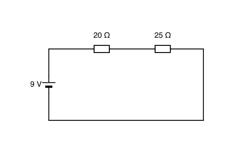
A 9 V battery is connected in series with two resistors: one of 20 Ω and one of 25 Ω. Calculate the total resistance of the circuit and the current flowing through it.
Solution:
- Total resistance: R_total = R₁ + R₂ = 20 + 25 = 45 Ω
- Rearrange V = IR to give I = V / R
- I = 9 / 45 = 0.20 A
4. Current-voltage (I-V) graphs
What an I-V graph shows
- An I-V graph plots the current through a component (y-axis) against the voltage across it (x-axis), with the voltage varied from negative through zero to positive
- The shape of the line tells you how the component's resistance changes with the voltage applied:
- A straight line through the origin means the current is directly proportional to the voltage. The resistance is constant (this is ohmic behaviour)
- A curved line through the origin means the current is not directly proportional to the voltage. The resistance is variable (this is non-ohmic behaviour)
- The resistance at any point on an I-V graph is given by R = V / I, not by the gradient. (For an ohmic conductor R = 1/gradient because the line is straight, but in general the V/I ratio at each point is what matters.)
Common exam question
Using an I-V graph to find a resistance
Question: Use the current-voltage graph to determine the resistance of the component when the voltage across it is a given value (3–5 marks).
Read the current at that voltage off the curve (a reading within a small tolerance is accepted), then put it with the voltage into V = IR and rearrange. The three-mark version credits the substitution, the rearrangement (R = V/I seen anywhere earns it) and the evaluation; the five-mark version credits the equation, the reading, the substitution or rearrangement, the evaluation and a matching unit. Set in 2 of the 24 papers. The resistance is the ratio V/I at that point, not the gradient of the curve.
When the current axis is in milliamps, convert to amps (or give the answer in kilohms): a power-of-ten slip costs a mark, and the unit you write must match the number. For comparison, a fixed resistor's line is straight through the origin, and doubling the resistance halves the gradient.
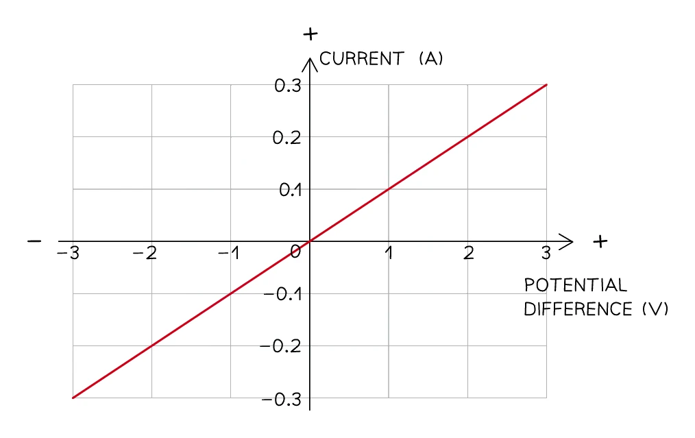
I-V graph for a fixed resistor (or a metal wire at constant temperature)
- A straight line through the origin, because current and voltage are directly proportional, in both polarities
- The slope is the same everywhere, so the resistance is the same everywhere; fixed resistors and wires at a steady temperature are ohmic conductors
I-V graph for a filament lamp
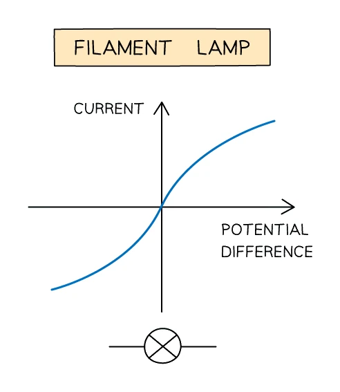
- The curve passes through the origin, but it flattens off as the voltage and current grow; the same shape appears in reverse on the negative side
- A flatter slope corresponds to a higher resistance (because R = V / I and V grows faster than I)
- The physics: a larger current heats the filament; the metal ions then vibrate more vigorously, scattering the drifting electrons more often, so the resistance climbs
- A filament lamp is therefore a non-ohmic component, because its resistance is not constant across its working range
Common exam question
Why a filament lamp's I-V graph is a curve
Question: Describe the relationship shown by a filament lamp's current-voltage graph, or explain why the current is not proportional to the voltage (2 marks).
For describe: the current increases as the voltage increases (one mark), and the relationship is non-linear, the gradient decreasing so that the current rises ever more slowly (second mark). Calling it proportional forfeits that second mark. Asked in 3 of the 24 papers.
For explain, any two of three ideas score: the current heats the filament; its resistance increases with temperature; so for the same voltage the current is lower, which is what bends the graph. "Lamp" is condoned for "filament", but "it heats up" alone is one idea, not two. A straight line through the origin means the component is a resistor (an ohmic conductor), not a lamp, unless the lamp has not yet warmed enough for its graph to curve. "It does not obey Ohm's law" is not one of the three ideas, although the phrase does score when a question asks whether a straight-line graph could belong to a lamp.
I-V graph for a semiconductor diode
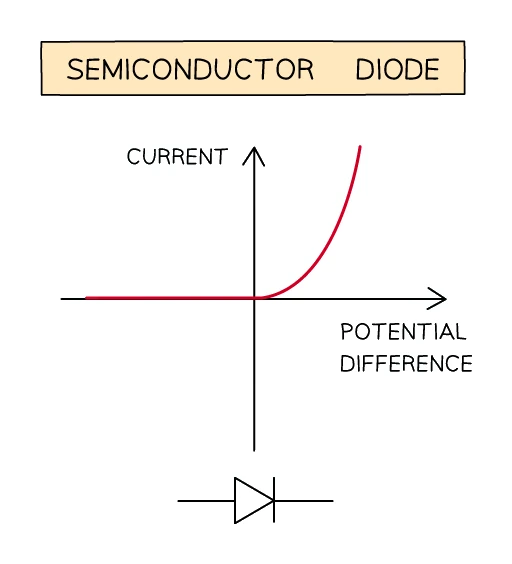
- The diode is a one-way conductor: it lets current pass in the direction of its arrowhead symbol only, which is called forward bias
- In forward bias, almost no current flows until the voltage exceeds about 0.6–0.7 V; past that threshold, the current climbs very sharply with very little extra voltage. The resistance is effectively infinite below the threshold and very small above it
- In reverse bias, no current flows at all (over the normal operating range); the diode's resistance is enormous
- The I-V graph therefore sits flat on the V axis for negative V, hugs the V axis from 0 to about 0.6 V, then rises almost vertically
Investigating an I-V curve in the lab
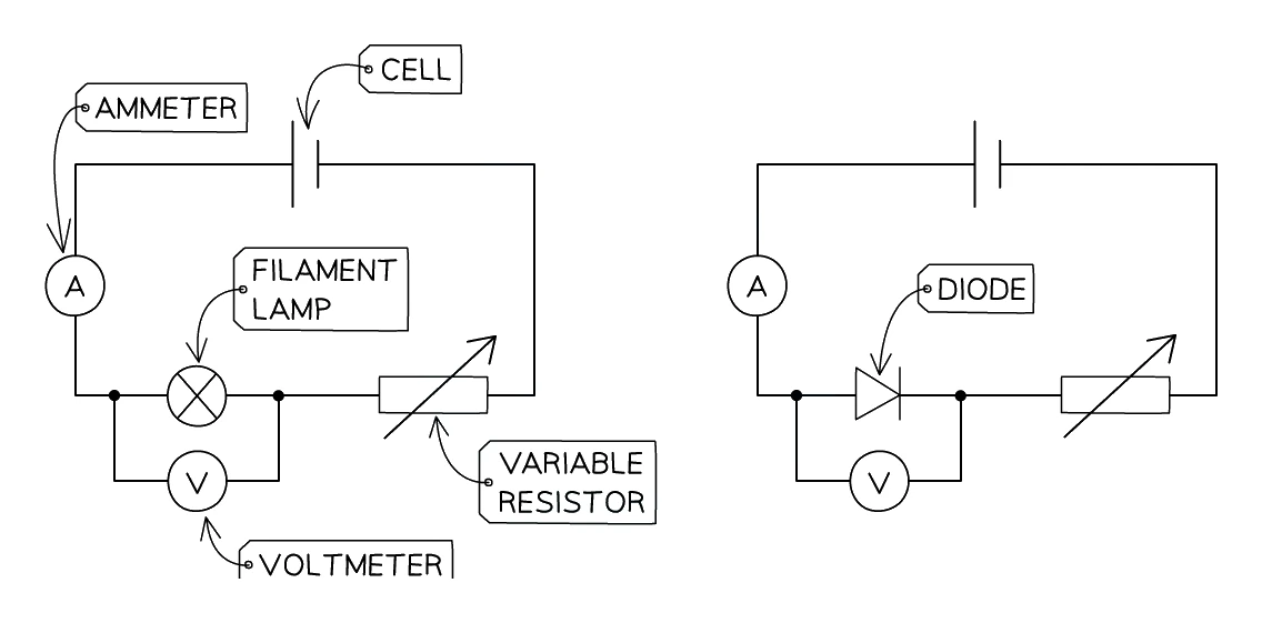
- Apparatus:
- the component under test (resistor, filament lamp or diode)
- an ammeter wired in series with the component to read the current through it
- a voltmeter wired in parallel across the component to read the voltage across it
- a variable resistor in series with the component to vary the current
- a cell or low-voltage supply
- Method:
- Build the circuit and set the variable resistor to its highest resistance (so the initial current is small)
- Record the voltmeter and ammeter readings
- Reduce the resistance of the variable resistor by a small step; record V and I again
- Repeat until a wide range of voltages has been swept (do not exceed the rated voltage of the component, or it may burn out)
- To capture the negative side of the curve, reverse the cell's connections and repeat
- Plot I against V with the recorded data points and join them with a smooth curve
Common exam question
Drawing the circuit for a current-voltage investigation
Question: Draw, complete or describe a circuit a student could use to investigate how the current in a component varies with the voltage across it, usually from a list of equipment (3–4 marks).
The four marks: correct symbols in a complete circuit; the variable resistor in series with the component (a variable power supply or potential divider is accepted); the ammeter in series with it; the voltmeter in parallel across the component only. Asked in 7 of the 24 papers. A voltmeter across the variable resistor and the component together is rejected, an imperfect but identifiable meter symbol is condoned, and a thermistor or LDR offered as the means of variation is ignored.
Asked to describe the method instead, say what you measure (current and voltage), how you vary it (adjust the variable resistor), that you repeat and average each reading, and that you switch off between readings so the component does not heat up.
5. Components whose resistance changes
Thermistors
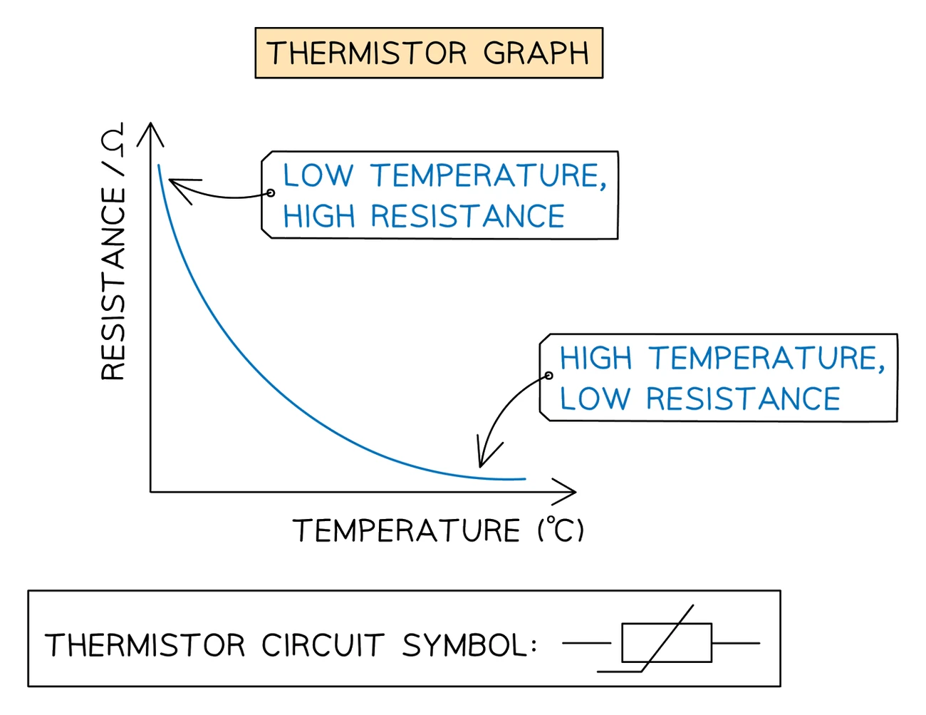
- A thermistor is a resistor whose resistance changes with temperature
- The standard schoolroom thermistor is a negative-temperature-coefficient (NTC) thermistor:
- resistance is high in cold conditions
- resistance is low in hot conditions
- The relationship is non-linear; a graph of resistance against temperature falls steeply at low temperatures and then levels off at high ones
- Uses include thermostats for ovens, fridges and central-heating systems; fire alarms; and temperature sensors in electronics
Light-dependent resistors (LDRs)
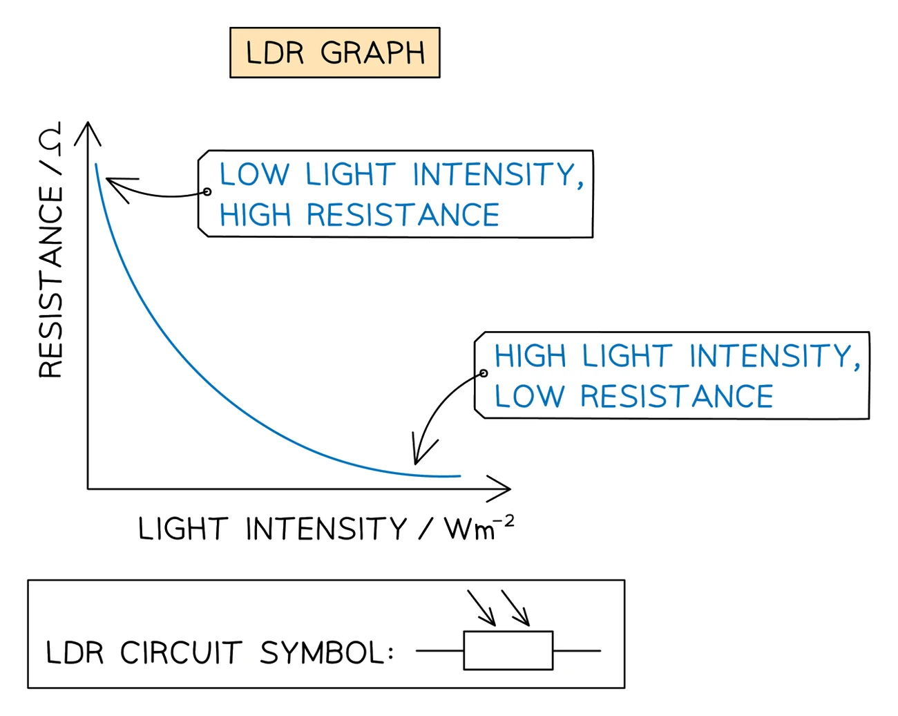
- A light-dependent resistor (LDR) is a resistor whose resistance changes with the light intensity falling on it:
- resistance is high in dark conditions
- resistance is low in bright conditions
- The relationship is again non-linear; a graph of resistance against light intensity falls steeply as the light first grows brighter and then levels off
- Uses include automatic street lamps that switch on at dusk, dawn-detection circuits in alarm clocks, and the light meters in cameras
Common exam question
Explaining the effect of a change in light or temperature
Question: Explain what happens to the brightness of a lamp, or to a voltmeter reading, when an LDR in the circuit is covered or the room containing a thermistor cools (2–3 marks).
Start with the component: covering an LDR, or cooling a thermistor, increases its resistance; the resistance of the circuit therefore rises, so the current falls; so the lamp is dimmer, or a voltmeter across the fixed resistor reads less (one across the thermistor or LDR would read more). State the change and give the chain, because each step is a mark. Set in 2 of the 24 papers. Explaining a dimmer lamp by the paper covering the lamp itself is rejected.
Asked to describe the thermistor's graph, say its resistance decreases as temperature increases and that the relationship is non-linear; "inversely proportional" earns both marks. An unnamed component whose resistance falls as the light gets brighter is a light-dependent resistor.
Lamps and light-emitting diodes (LEDs)
- A filament lamp lights up when current flows through it, because the filament heats up enough to glow white-hot. Lamps are non-ohmic (their resistance climbs as they get hot) but they conduct current in either direction
- A light-emitting diode (LED) is a special kind of diode that emits light when current flows through it in forward bias
- Like any diode, an LED conducts in one direction only; mounted backwards in a circuit, it simply does not light up
- LEDs are widely used as indicator lights because they need very little current to be visibly on, last for years and produce very little heat
- An LED's standard symbol is a diode triangle with two small arrows pointing outwards, meaning light leaves the device. The LDR's symbol carries two small arrows pointing inwards, meaning light is arriving at the resistor
Common exam question
Using an LED to show that a current is flowing
Question: Give a reason why an LED is included in a circuit, draw an LED that will indicate when there is a current in one particular component, or explain why an LED on an a.c. supply flashes (1–2 marks).
The reason is that the LED shows a current is present (for example that a fuse is still intact): one mark. To indicate the current in one component, draw the LED in the branch that contains only that component (one mark) and the right way round, arrowhead pointing the way the conventional current flows (second mark); an LED in the main part of the circuit would light whenever any branch carried a current. Asked in 3 of the 24 papers.
On an a.c. supply the current keeps changing direction, and an LED conducts in one direction only, so it is unlit during each reverse half-cycle: that is why it flashes.