1. What Boolean logic is
Boolean logic is a system in which every value is either TRUE or FALSE, written as 1 or 0. A logic gate takes one or more Boolean inputs and produces a single Boolean output by applying a fixed rule.
Inside every digital computer the underlying signals are voltages. A high voltage stands for 1 (TRUE) and a low voltage stands for 0 (FALSE). Every arithmetic, control or decision step in the processor is built from logic gates that combine these 1s and 0s.
There are exactly six logic gates to learn: AND, OR, NOT, XOR, NAND and NOR. Each gate has:
- a rule that says what its output is for any combination of inputs,
- a circuit symbol used in logic diagrams,
- a Boolean notation used inside expressions,
- a that lists the output for every possible input combination.
Inputs are usually labelled A, B, C; outputs are usually labelled Q, X or Z.
2. The six logic gates
For each gate the format is the same: the circuit symbol, the rule in plain English, the Boolean notation (Cambridge papers and mark schemes write it with the words AND, OR, NOT, NAND, NOR and XOR), and the truth table.
AND
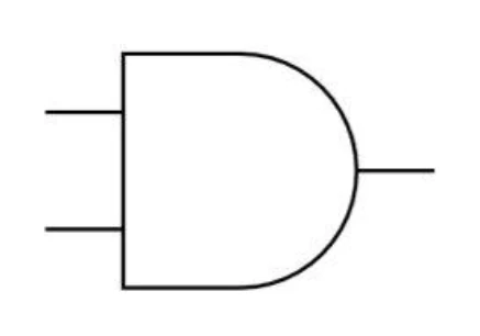
Rule: the output is 1 only when every input is 1. If any input is 0, the output is 0.
| Boolean notation | Read aloud |
|---|---|
A · B, AB, A ∧ B | "A AND B" |
| A | B | A AND B |
|---|---|---|
| 0 | 0 | 0 |
| 0 | 1 | 0 |
| 1 | 0 | 0 |
| 1 | 1 | 1 |
A quick way to remember the rule: an AND gate is like two switches in series; current only flows through if both are closed.
OR
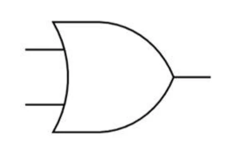
Rule: the output is 1 when at least one input is 1. The output is 0 only when every input is 0.
| Boolean notation | Read aloud |
|---|---|
A + B, A ∨ B | "A OR B" |
| A | B | A OR B |
|---|---|---|
| 0 | 0 | 0 |
| 0 | 1 | 1 |
| 1 | 0 | 1 |
| 1 | 1 | 1 |
Think of an OR gate as two switches in parallel: closing either one (or both) lets current flow.
NOT
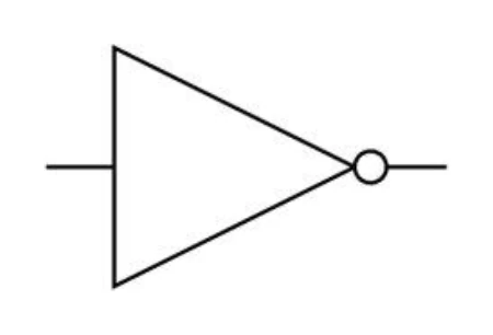
Rule: the output is the inverse of the input. A 1 becomes a 0; a 0 becomes a 1. NOT has exactly one input.
| Boolean notation | Read aloud |
|---|---|
¬A, A̅, NOT A | "NOT A" |
| A | NOT A |
|---|---|
| 0 | 1 |
| 1 | 0 |
A NOT gate is also called an because it flips its input.
XOR (exclusive OR)
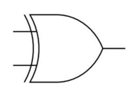
Rule: the output is 1 when exactly one input is 1. If both inputs are the same (both 0 or both 1), the output is 0.
| Boolean notation | Read aloud |
|---|---|
A ⊕ B, A XOR B | "A XOR B" |
| A | B | A XOR B |
|---|---|---|
| 0 | 0 | 0 |
| 0 | 1 | 1 |
| 1 | 0 | 1 |
| 1 | 1 | 0 |
The easiest way to keep XOR straight: the output is 1 when the inputs differ, and 0 when they match.
NAND (NOT AND)
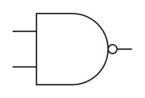
Rule: the output is the opposite of AND. NAND outputs 0 only when every input is 1; in every other case the output is 1.
| Boolean notation | Read aloud |
|---|---|
¬(A · B), A NAND B | "A NAND B" |
| A | B | A NAND B |
|---|---|---|
| 0 | 0 | 1 |
| 0 | 1 | 1 |
| 1 | 0 | 1 |
| 1 | 1 | 0 |
NAND is drawn as an AND gate with a small circle on the output. The circle is the "NOT bubble" and it flips the result.
NOR (NOT OR)
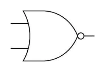
Rule: the output is the opposite of OR. NOR outputs 1 only when every input is 0; in every other case the output is 0.
| Boolean notation | Read aloud |
|---|---|
¬(A + B), A NOR B | "A NOR B" |
| A | B | A NOR B |
|---|---|---|
| 0 | 0 | 1 |
| 0 | 1 | 0 |
| 1 | 0 | 0 |
| 1 | 1 | 0 |
NOR is drawn as an OR gate with the same NOT bubble on the output.
Side-by-side comparison
It is worth memorising this single table; almost every logic-gates question depends on it.
| A | B | AND | OR | XOR | NAND | NOR |
|---|---|---|---|---|---|---|
| 0 | 0 | 0 | 0 | 0 | 1 | 1 |
| 0 | 1 | 0 | 1 | 1 | 1 | 0 |
| 1 | 0 | 0 | 1 | 1 | 1 | 0 |
| 1 | 1 | 1 | 1 | 0 | 0 | 0 |
Two patterns are worth noticing:
- The NAND column is the AND column with every value flipped.
- The NOR column is the OR column with every value flipped.
That is exactly what the "N" in NAND and NOR means.
3. Circuit symbols
Each gate has a standard circuit symbol. In the exam these are drawn quickly, so it helps to be able to recognise them by their outline.
- AND: a flat-back D-shape. Inputs enter the flat side, the rounded tip is the output.
- OR: a shield shape. The back (the input side) curves inward and the front sweeps to a point.
- NOT: a small triangle pointing right, with a circle (the "NOT bubble") on the tip.
- NAND: an AND symbol with a NOT bubble added to its output.
- NOR: an OR symbol with a NOT bubble added to its output.
- XOR: an OR symbol with an extra curved line behind the back, forming a doubled curve.
The NOT bubble (a small circle on a gate's output) always means "invert what comes out". That is how NAND, NOR and many circuit fragments mark a negation.
Common exam question
Matching logic gates to their symbols
Question: Draw a line from each of four named logic gates to its symbol, choosing from five symbols so that one is left over (4 marks).
Asked in 2 of the 17 papers, with one mark for each correct line. Both papers listed AND and NAND among the four gates; the other two were OR and NOT in one paper, NOR and XOR in the other. Each pair differs by a single detail, so check two places on every symbol before you draw its line: the output end (a bubble turns AND into NAND and OR into NOR) and the back (flat for AND and NAND, curved for OR and NOR, doubled for XOR). NOT is the only triangle.
4. Reading a Boolean expression
A logic expression is just an equation that describes a circuit. The output is on the left of =; the inputs and gate operators are on the right. Brackets control the order in which the gates act.
Order of evaluation (always evaluate inside out): innermost brackets first, then NOT, then AND, then OR.
5. Setting up a truth table
A truth table lists every possible combination of inputs alongside the output the circuit produces.
Number of rows. A truth table for
ninputs always has 2ⁿ rows: 4 rows for 2 inputs, 8 rows for 3 inputs, 16 rows for 4 inputs.
To fill in the input columns without missing any combination, count up in binary from 0:
- For 2 inputs (
A,B): 00, 01, 10, 11. - For 3 inputs (
A,B,C): 000, 001, 010, 011, 100, 101, 110, 111.
A practical trick: the right-most column alternates every row (0, 1, 0, 1, …); the next column alternates every two rows (0, 0, 1, 1, …); the next alternates every four rows. That guarantees every combination appears exactly once.
Exam circuits use at most three inputs and produce a single output, so the largest table you will be asked to fill has 8 rows.
6. Working out a circuit's output for given inputs
When the question gives you a circuit and a specific set of input values (for example A = 1, B = 0, C = 1), the safest method is to process the gates from left to right, in the order the signals flow. In the circuit below, an OR gate combines A and B, a NOT gate inverts C, and an AND gate combines those two results to give the output P.
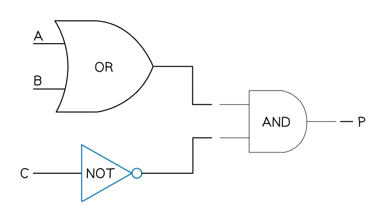
Method. (1) Mark each input on the diagram with its 0 or 1. (2) For each gate, look only at the values arriving at its inputs and apply the gate's rule to get its output. (3) Pass that output forward as one of the inputs to the next gate. (4) Repeat until you reach the final output
P.
Always write down the intermediate value at the output of every gate, even if you can do the calculation in your head. Only the outputs are marked, so the intermediates earn nothing on their own, but writing them down is what stops one slip from spoiling the answer.
7. Constructing a truth table for a multi-gate circuit
For longer questions the examiner gives a logic expression or a circuit and asks for the truth table for every input combination. The cleanest method is to add one column per gate in the order the signals flow, then fill in the table row by row.
Method. (1) Write down every input combination (2ⁿ rows). (2) In the working space beside the table, add an intermediate column for each internal gate, named after its sub-expression (
A AND B) or numbered (Gate 1,Gate 2). (3) Fill in each intermediate column by applying the gate's rule to its input columns, row by row. (4) The final-output columnQis built from whatever feeds the last gate, using its rule.
Common exam question
Completing a truth table
Question: Complete the truth table for a given logic expression, logic circuit or worded problem with three inputs (4 marks).
Asked in 8 of the 17 papers, always for 4 marks: five times from an expression, twice from a circuit, once from a worded problem. The eight input rows are printed in binary order (beside a working space, except in the worded problem), and only the output column is marked: eight correct outputs earn 4, six or seven 3, four or five 2, two or three 1. Intermediate columns earn nothing, so keep them in the working space to stop slips.
When the table follows a part asking you to draw the circuit or write the expression, work from what the question printed, not from your own answer. For a worded problem, read each input's 0 and 1 from the key: an input goes through a NOT only when the condition needs it to be 0 (off, or not happening).
Worked example
Completing the truth table for a multi-gate circuit
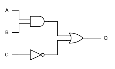
The logic circuit shown has three inputs, A, B and C, and one output, Q. An AND gate combines A and B, a NOT gate inverts C, and an OR gate combines those two results to give Q. Complete the truth table.
Solution:
In the working space, add one column per gate (A AND B and NOT C), then work out Q row by row.
| A | B | C | A AND B | NOT C | Q |
|---|---|---|---|---|---|
| 0 | 0 | 0 | 0 | 1 | 1 |
| 0 | 0 | 1 | 0 | 0 | 0 |
| 0 | 1 | 0 | 0 | 1 | 1 |
| 0 | 1 | 1 | 0 | 0 | 0 |
| 1 | 0 | 0 | 0 | 1 | 1 |
| 1 | 0 | 1 | 0 | 0 | 0 |
| 1 | 1 | 0 | 1 | 1 | 1 |
| 1 | 1 | 1 | 1 | 0 | 1 |
- A AND B is 1 only in the final two rows, where both A and B are 1.
- NOT C is 1 whenever C is 0 (rows 1, 3, 5 and 7) and 0 whenever C is 1.
- Q is 1 whenever at least one of those two values is 1, and 0 only where both are 0.
- So Q is 0 in rows 2, 4 and 6 and 1 in the other five rows.
Only the Q column is marked, so copy it into the printed table and leave the working columns in the working space.
Worked example
Completing a truth table from a problem statement
A garden sprinkler S comes on when the soil is dry and it is not raining, or whenever the manual override is switched on. The signals are coded like this:
| Signal | 0 | 1 |
|---|---|---|
| Soil D | moist | dry |
| Rain R | not raining | raining |
| Override M | off | on |
| Sprinkler S | off | on |
Complete the truth table for this problem.
Solution:
- Turn each condition into a value from the key: soil dry is D = 1, not raining is R = 0 (so R goes through a NOT), and override on is M = 1.
- That gives
S = (D AND NOT R) OR M, worked with one extra column for the bracket.
| D | R | M | D AND NOT R | S |
|---|---|---|---|---|
| 0 | 0 | 0 | 0 | 0 |
| 0 | 0 | 1 | 0 | 1 |
| 0 | 1 | 0 | 0 | 0 |
| 0 | 1 | 1 | 0 | 1 |
| 1 | 0 | 0 | 1 | 1 |
| 1 | 0 | 1 | 1 | 1 |
| 1 | 1 | 0 | 0 | 0 |
| 1 | 1 | 1 | 0 | 1 |
- Every row with M = 1 gives S = 1; when M = 0, S is 1 only where D = 1 and R = 0.
- So S is 1 in rows 2, 4, 5, 6 and 8 and 0 in rows 1, 3 and 7.
8. Drawing a logic circuit from a Boolean expression
The opposite direction is also examined: you are given a Boolean expression and have to draw the circuit.
Method. (1) Read the expression inside out: innermost brackets first, then NOT, then AND, then OR. (2) Use one gate per operator. (3) Wire each gate's inputs to the correct preceding signal (a labelled input variable, or the output of an earlier gate). (4) Make sure NOT gates appear before the negated value enters its next gate. (5) Label the last gate's output
Q(or whatever name the question uses).
Common exam question
Drawing a logic circuit from an expression
Question: Draw a logic circuit for a given logic expression without simplifying it, using no gate with more than two inputs (4–5 marks).
Asked in 4 of the 17 papers, always followed by a truth table for the same expression. Each correct gate wired to the correct inputs earns one mark, so the marks match the number of operators (four in three papers, five in the other). Check that your circuit has one gate per operator, each drawn as its own standard symbol: NAND, NOR and XOR are single gates.
In all four papers one input appears twice in the expression but is printed once on the left: branch its line to both gates. A NOT before a single letter goes on that input; a NOT before a bracket goes on the output of that bracket's gate. One paper wrote it as conditions (A = 1 for A, C = NOT 1 for NOT C): translate each before you draw.
Worked example
Turning an expression into a four-gate circuit
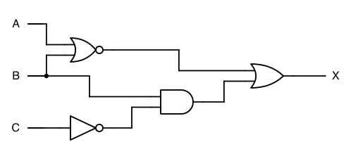
Draw a logic circuit for X = (A NOR B) OR (NOT C AND B). Each gate may have at most two inputs, and the expression must not be simplified.
Solution:
- Count the operators: NOR, NOT, AND and OR, so the circuit needs four gates.
- Gate 1: a NOR gate with inputs A and B.
- Gate 2: a NOT gate on input C. The NOT stands in front of the single letter C, so it inverts C alone.
- Gate 3: an AND gate fed by Gate 2 and by B. B is printed only once on the left, so branch its line to reach both Gate 1 and Gate 3.
- Gate 4: an OR gate fed by Gates 1 and 3, whose output is X.
- The finished circuit has four gates (NOR, NOT, AND, OR), with B branching to Gates 1 and 3 and Gate 4's output labelled X
9. Going the other way: writing the expression for a circuit
Sometimes a question gives the circuit and asks for the Boolean expression. The method is the mirror image of section 8.
Method. (1) Label each gate's output left to right. (2) Write the expression for each labelled output in terms of the inputs feeding it. (3) Substitute into the final output's expression so that everything is expressed in terms of the original inputs.