1. What a Boolean expression is
Topic 26 covered the six logic gates as physical components: AND, OR, NOT, XOR, NAND, NOR. This topic covers the same gates as algebra: how to write them as expressions, derive them from circuits or truth tables, and evaluate them for given inputs.
A Boolean expression is an algebraic statement built from Boolean variables (each
0or1), the operators NOT, AND, OR, NAND, NOR and XOR, and brackets. Every expression evaluates to a single Boolean value,0or1.
The output of a logic circuit can always be written as a Boolean expression in its inputs. Working the other way, every Boolean expression has a corresponding logic circuit and a corresponding truth table. The three representations are interchangeable; choosing the right one for a question is half the work.
2. Boolean notation
Cambridge papers and mark schemes for this syllabus write logic expressions in words (the word form below), so write your answers the same way. The other two columns show the symbols that other books use, so that you can read them.
| Operator | Word form | Algebraic form | Other forms |
|---|---|---|---|
| AND | A AND B | A · B | AB, A ∧ B |
| OR | A OR B | A + B | A ∨ B |
| NOT | NOT A | ¬A | A̅ (overbar), A' |
| NAND | A NAND B | ¬(A · B) | (A · B)', overbar over the bracket |
| NOR | A NOR B | ¬(A + B) | (A + B)', overbar over the bracket |
| XOR | A XOR B | A ⊕ B | (A · ¬B) + (¬A · B) |
A few important conventions:
- The dot
·for AND is often dropped, just like in ordinary algebra. SoABmeans "A AND B", andAB + Cmeans(A AND B) OR C. +here means OR, not numerical addition.1 + 1in Boolean algebra is1, not2.- An overbar over a variable (or group of variables) means NOT. The mark schemes for this syllabus write the word NOT instead.
- Variables are always single letters. Take them from the question: inputs are often
A,BandCbut can be other letters (such asP,Q,RorX,Y,Z), and in the papers the output is usuallyX,ZorW.
(highest to lowest): brackets → NOT → AND → OR.
This mirrors school algebra: brackets first, then unary −, then ×, then +. As in algebra, brackets remove all ambiguity, so when in doubt, add brackets.
3. Deriving an expression from a logic circuit
Given a circuit, the safest method is to label each gate's output with its Boolean sub-expression, working from the inputs through to the final output.
Method. (1) Identify each gate and the signals feeding it. (2) Working left to right, write the output of each gate as a Boolean sub-expression using its input labels. (3) Use that sub-expression as the input to any gate it feeds. (4) The final gate's output is the expression for
Q.
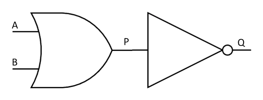
A circuit to work through: label the OR gate's output P, and the following NOT gate then gives the final output Q.
Common exam question
Writing a logic expression for a circuit
Question: Write a logic expression for the logic circuit shown, without simplifying it (3–4 marks).
Asked in 2 of the 17 papers, both on Paper 2. Work from the inputs to the output: write each gate's output as a sub-expression (in brackets for a two-input gate) and carry it into the gate it feeds. Write it in words (NOT, AND, OR, NAND, NOR, XOR), as both mark schemes do.
The marks build up with the expression: one for each piece as the gates join (such as the NOT on an input, then the gate that NOT feeds), and the last only for the complete expression. So copy the wiring gate for gate rather than simplifying it. One scheme accepted the two halves of the final OR either way round.
A NOT on a single input is just NOT A. A NOT after a two-input gate needs brackets, NOT (A AND B), because NOT A AND B inverts A alone.
Worked example
Writing the expression for a four-gate circuit
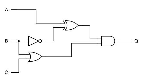
The logic circuit shown has inputs A, B and C and output Q. A NOT gate inverts B, and an XOR gate combines A with that NOT gate's output. An OR gate combines B and C. An AND gate combines the outputs of the XOR and OR gates to give Q. Write a logic expression for Q without simplifying it.
Solution:
- Gate 1, the NOT gate on input B, gives
NOT B. It inverts a single letter, so it needs no brackets. - Gate 2, the XOR gate, takes A and the output of gate 1:
(A XOR NOT B) - Gate 3, the OR gate, takes B and C:
(B OR C). B is drawn once on the left and branches to gates 1 and 3. - Gate 4, the AND gate, joins gates 2 and 3, so Q = (A XOR NOT B) AND (B OR C)
Four gates give four operators (NOT, XOR, OR and AND), a quick check that no gate has been missed.
4. Deriving an expression from a truth table
When the question gives you a truth table and asks for the Boolean expression, the standard method is: write one AND term per row where the output is 1, then OR all those AND terms together.
Method. (1) Find every row where
Q = 1. (2) For each such row, write an AND term that is true on that row only: use the variable directly when its value in that row is1, andNOT variablewhen its value is0. (3) OR all the AND terms together.
5. Evaluating a Boolean expression for given inputs
The reverse problem: you are given an expression and specific values for its variables, and have to compute the output.
Method. (1) Substitute each variable with its given
0or1. (2) Apply operators in precedence order: brackets first, then NOT, then AND, then OR. (3) Write down every intermediate value rather than doing the whole thing in your head.
6. The two-way road: expression ↔ circuit ↔ truth table
The three representations of a Boolean function can be converted in any direction. Each conversion has been covered above, but it helps to see them together.
| From → to | Method (covered in) |
|---|---|
| Circuit → expression | Label each gate's output with its sub-expression, working left to right (section 3). |
| Truth table → expression | One AND term per Q = 1 row, OR them together (section 4). |
| Expression → truth table | Evaluate the expression for every possible combination of inputs (section 5, repeated for each row). |
| Expression → circuit | One gate per operator; bracket innermost first; NOT gates before the negated signal feeds its next gate (covered in topic 26). |
| Circuit → truth table | Trace signals through each gate for every input row, adding intermediate columns (covered in topic 26). |
| Truth table → circuit | Derive the expression from the truth table, then draw the circuit for that expression. |
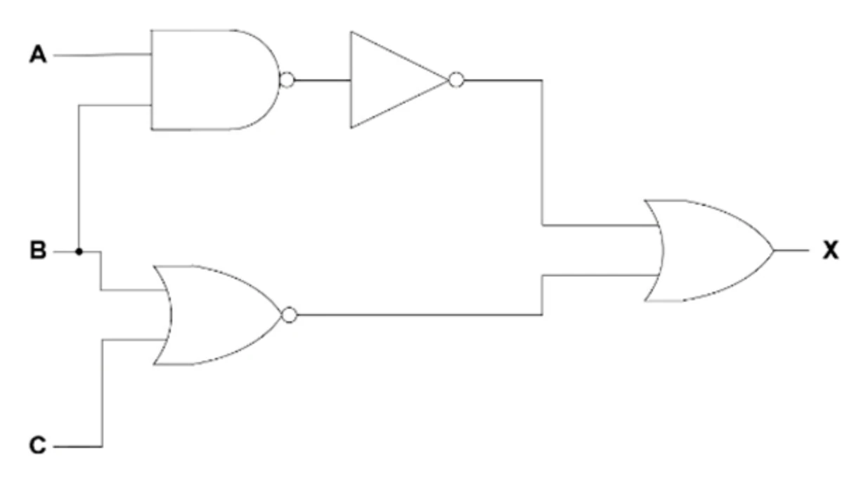
The circuit below can be taken either way: label each gate's output to build the Boolean expression for X, or trace every input combination through the gates to fill in its truth table.
Whatever route the exam asks for, the key check is the same: at the end, the truth table of the new representation must agree with the truth table of the original, row for row.